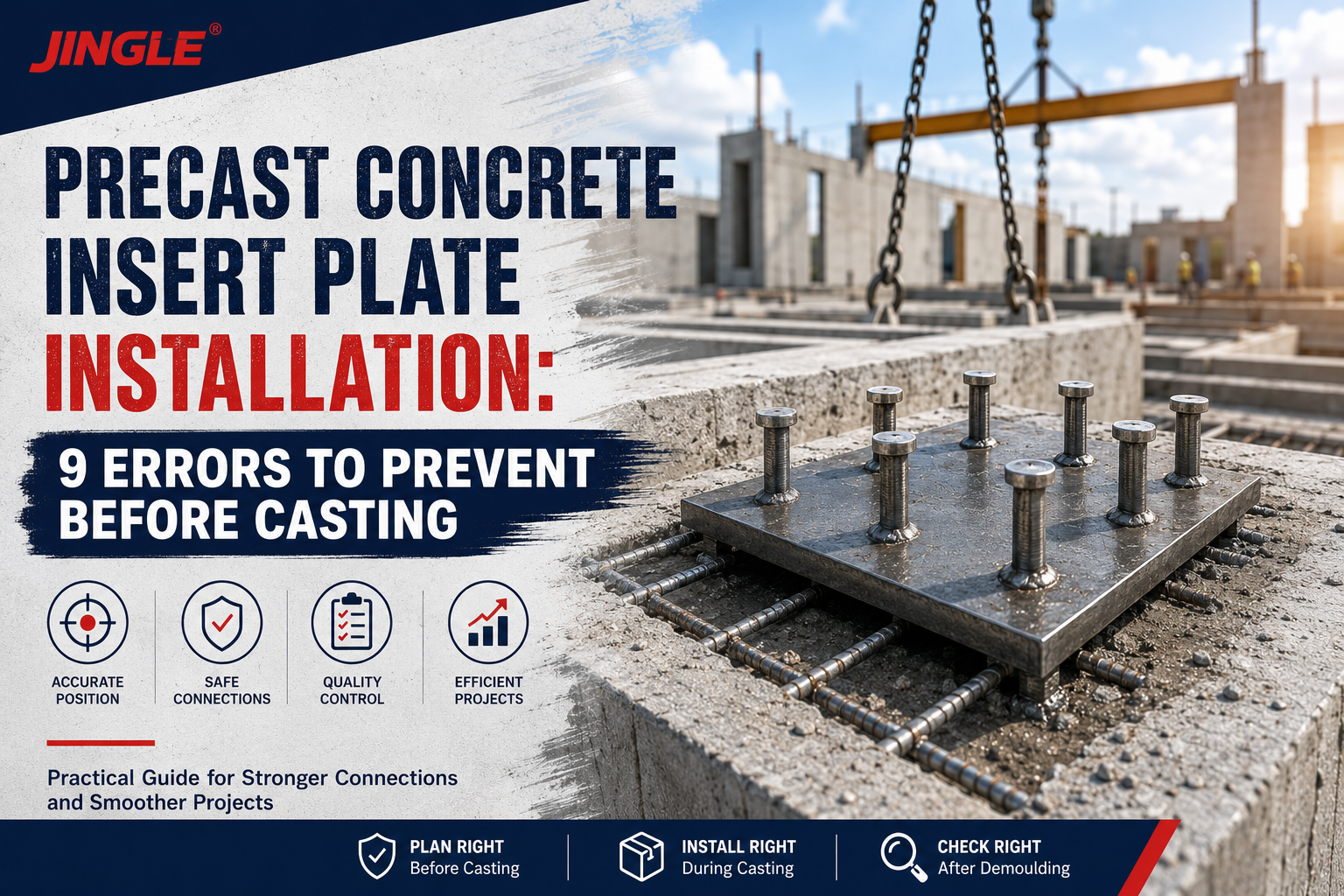
Precast Concrete Insert Plate Installation: 9 Errors to Prevent Before Casting

A precast concrete insert plate with welded studs can be manufactured correctly and still fail to serve its intended purpose if it is installed in the wrong position before casting.
Unlike a post-installed anchor, a cast-in plate becomes difficult and expensive to adjust after the concrete has cured. A few millimeters of displacement may interfere with a steel bracket, façade connection, handrail, machinery support, or adjoining precast element.
Reliable precast concrete insert plate installation therefore requires more than placing the component inside the mould. The installer must control drawing revisions, reinforcement clearances, plate orientation, temporary fixation, concrete consolidation, exposed-surface protection, and final inspection.
This guide explains nine common installation errors, how they affect the finished connection, and what contractors, precast factories, engineers, and purchasing teams should confirm before production.
Quick Answer
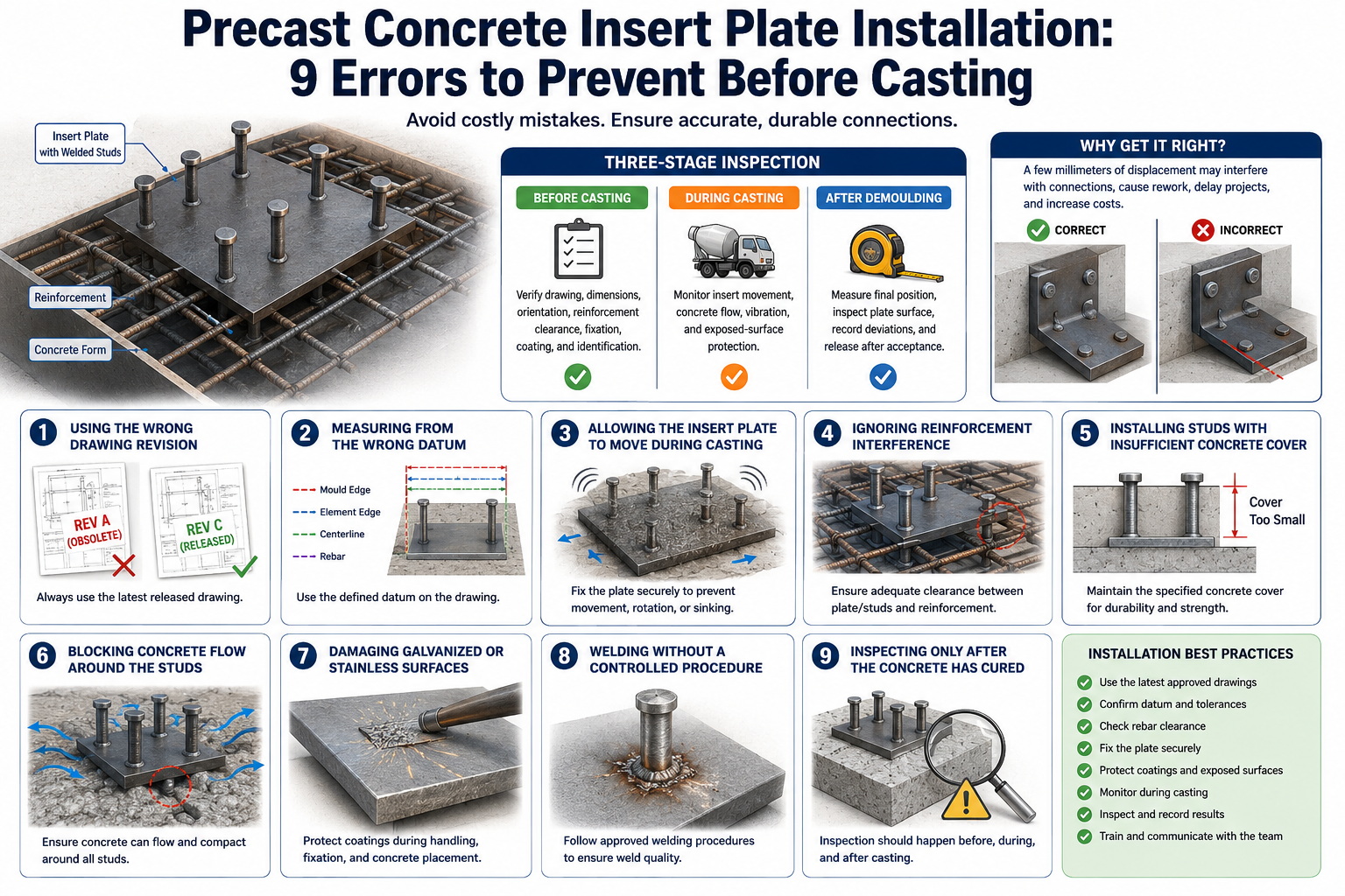
The most common precast concrete insert plate installation errors are:
-
Using an outdated drawing revision
-
Measuring from the wrong datum
-
Allowing the plate to move during casting
-
Ignoring reinforcement interference
-
Installing studs with insufficient concrete cover
-
Blocking concrete flow around the studs
-
Damaging galvanized or stainless surfaces
-
Welding without a controlled procedure
-
Inspecting only after the concrete has cured
The most effective control method is a three-stage inspection:
-
Before casting: verify the drawing, dimensions, orientation, reinforcement clearance, fixation, coating, and identification.
-
During casting: monitor insert movement, concrete flow, vibration, and exposed-surface protection.
-
After demoulding: measure the final position, inspect the plate surface, record deviations, and release the element only after acceptance.
1. Using the Wrong Drawing Revision
A dimensional inspection has little value if the production team is checking against an obsolete drawing.
Customized embedded plates may be revised because of:
-
Changes to the supporting bracket
-
Revised structural loads
-
Different reinforcement spacing
-
Changes in concrete element thickness
-
Modified stud length or quantity
-
New holes or slots
-
Updated coating requirements
-
Adjusted installation tolerances
If purchasing, fabrication, reinforcement preparation, and mould setup are working from different revisions, the resulting assembly may be impossible to install even when each team believes its own work is correct.
How to prevent it
The released drawing should display:
-
Drawing number
-
Revision number
-
Approval status
-
Release date
-
Plate part number
-
Concrete element reference
-
Defined measurement datum
-
Relevant tolerances
Superseded drawings should be removed from production areas. The approved drawing revision should also appear on the purchase order, inspection record, and product label where practical.
For customized products, do not begin mass production based only on an email image or an unapproved sketch.
2. Measuring from the Wrong Datum
A datum is the agreed reference point, line, or surface from which dimensions are measured. Without a common datum, two inspectors can measure the same insert and obtain apparently conflicting results.
For example, the plate position might be measured from:
-
The mould edge
-
The concrete element edge
-
A centerline
-
A reinforcement reference
-
An architectural surface
-
Another embedded component
These points are not interchangeable. Mould dimensions, chamfers, recesses, and production allowances can create differences between the mould edge and the finished concrete edge.
Recommended drawing information
A precast embedded plate drawing should define:
-
Horizontal datum
-
Vertical datum
-
Plate centerline
-
Plate elevation
-
Rotation or angular orientation
-
Exposed-face level
-
Permitted positional tolerance
-
Permitted surface projection or recess
Measure from stable production references rather than from reinforcement bars that may shift during cage assembly.
3. Allowing the Insert Plate to Move During Casting
Concrete placement creates forces that can move an inadequately fixed insert. Pump pressure, concrete flow, vibration, contact with a hose, and movement of the reinforcement cage can all change its position.
A plate that is correct before pouring may therefore be outside tolerance after demoulding.
Typical movement patterns
-
Plate shifts horizontally
-
Plate rotates within the mould
-
One edge lifts away from the form face
-
Studs tilt because the reinforcement cage moves
-
Plate sinks into the concrete
-
Fixing screws loosen during vibration
Fixation methods
Depending on the mould and plate design, temporary fixation may use:
-
Bolts through prepared plate holes
-
Magnets for steel moulds
-
Dedicated positioning brackets
-
Reusable jigs
-
Welded temporary supports, where approved
-
Clamps or external fixtures
-
Purpose-designed plastic positioning components
The fixation method must hold the plate without damaging the mould, coating, or final exposed surface.
A pre-pour check should include a physical stability test. The installer should confirm that the insert does not move when subjected to the level of contact reasonably expected during concrete placement.
4. Ignoring Reinforcement Interference
Studs, reinforcing bars, lifting anchors, cast-in channels, sockets, conduits, and other inserts often compete for limited space inside a precast element.
Moving a reinforcing bar on the production floor may appear to solve an immediate clash, but reinforcement changes can affect the structural design. Cutting, bending, or relocating reinforcement should not occur without approval from the responsible engineer.
Review the complete congestion zone
Before releasing the insert plate for production, check:
-
Stud-to-rebar clearance
-
Plate-to-rebar clearance
-
Concrete cover
-
Distance to concrete edges
-
Distance to lifting anchors
-
Distance to electrical conduits or sleeves
-
Space for concrete aggregate to pass
-
Access for the vibrator
-
Space for temporary fixing hardware
A coordinated 3D model is useful for complex elements, but a full-scale template or first-article fit check may identify practical installation problems that are easy to miss on a drawing.
Other precast concrete accessories installed in the same element should be reviewed as one coordinated system rather than as unrelated products.
5. Providing Insufficient Concrete Cover or Edge Distance
Longer studs do not automatically create a better connection. In a thin wall panel or slab, an unnecessarily long stud may reduce cover on the opposite face or interfere with reinforcement.
Similarly, positioning an insert too close to a concrete edge may increase the risk of local cracking, splitting, or breakout under load.
The acceptable embedment, spacing, edge distance, concrete strength, and reinforcement arrangement depend on the engineered connection. They should not be estimated by the installer or copied from an unrelated project.
The project’s adopted structural concrete requirements, which may include ACI 318 or another applicable design standard, should be confirmed by the responsible design professional.
Information the supplier needs
Provide:
-
Concrete element thickness
-
Specified concrete strength
-
Distance from the plate to each relevant concrete edge
-
Required stud length
-
Stud quantity and spacing
-
Reinforcement arrangement
-
Cracked or uncracked concrete assumptions, when relevant
-
Load directions and eccentricities
-
Fire, fatigue, or seismic requirements, if applicable
The insert plate supplier can manufacture the specified assembly, but approval of the complete load path remains an engineering responsibility.
6. Blocking Concrete Flow Around the Studs
Congestion below the plate can trap air and prevent the concrete from fully surrounding the studs. This is especially important when the plate is large, the studs are closely spaced, or the reinforcement cage is dense.
Potential consequences include:
-
Voids beneath the plate
-
Honeycombing
-
Incomplete stud embedment
-
Local surface defects
-
Reduced bond around anchoring components
-
Water paths near the embedded steel
Improve concrete placement
The production team should review:
-
Concrete placement direction
-
Aggregate size
-
Concrete workability
-
Space between studs
-
Access for vibration
-
Plate holes or venting provisions, if designed
-
Risk of segregation
-
Sequence of filling around congested areas
Do not add holes to an engineered plate on the production floor without approval. A hole may affect plate strength, corrosion protection, welding zones, or connection geometry.
During casting, vibration should consolidate the concrete without directly striking or displacing the insert assembly.
7. Damaging the Surface Finish
The surface treatment must match the exposure environment and the final connection method.
Common options include:
-
Plain carbon steel
-
Electro-galvanized steel
-
Hot-dip galvanized steel
-
Stainless steel
-
Project-specific coating systems
The Jinglefix product range lists plain, electro-galvanized, and hot-dip galvanized options for customized embedded plates. The required material and finish should be confirmed on the drawing rather than selected by appearance alone.
Common coating damage
Damage may occur through:
-
Grinding during fit-up
-
Uncontrolled temporary welding
-
Contact with lifting chains
-
Abrasion during transport
-
Concrete leakage onto the exposed face
-
Aggressive cleaning after demoulding
-
Storage in wet or contaminated conditions
For fabricated iron and steel articles, ISO 1461:2022 defines general properties and test methods for hot-dip galvanized coatings. The project should separately define required coating thickness, inspection locations, acceptable repair methods, and any areas intentionally left uncoated for field welding.
For stainless steel plates, use handling tools and work areas that minimize contamination from carbon-steel particles.
8. Welding Without a Controlled Procedure
Welding may take place during plate fabrication, during temporary fixation, or during final site connection. Each stage creates different risks.
Poorly controlled welding can cause:
-
Incomplete fusion
-
Cracking or porosity
-
Stud misalignment
-
Plate distortion
-
Damage to zinc coatings
-
Stainless-steel contamination
-
Reduced dimensional accuracy
-
Unapproved changes to the load path
The ISO 3834 series provides criteria for selecting appropriate quality requirements for fusion welding of metallic materials. The project may also specify another applicable structural welding standard.
Questions to confirm before welding
-
What welding standard applies?
-
Is a qualified welding procedure required?
-
Are the welder or operator qualifications current?
-
Can temporary attachments be welded to the plate?
-
Which areas must remain free from coating?
-
How will coating be repaired after welding?
-
What visual or nondestructive inspection is required?
-
How will weld repairs be documented?
-
Is heat distortion included in the dimensional inspection?
If the plate will be field welded after installation, the connection design should consider access, fire protection, ventilation, coating removal, coating repair, and the effect of heat on surrounding materials.
9. Waiting Until After Casting to Inspect
Post-cast inspection is necessary, but it is too late to correct many installation problems economically.
Once the concrete has cured, a displaced insert may require:
-
A redesigned connection bracket
-
Approved field modification
-
Additional post-installed anchors
-
Concrete repair
-
Local demolition and recasting
-
Rejection of the precast element
The most valuable inspection therefore occurs before the concrete is placed.
Precast Concrete Insert Plate Installation Checklist
Before casting
Verify:
-
Correct plate part number
-
Correct drawing revision
-
Plate length, width, and thickness
-
Material and surface treatment
-
Stud diameter, length, quantity, and layout
-
Weld condition
-
Plate orientation
-
Distance from the defined datums
-
Exposed-face level
-
Reinforcement clearance
-
Concrete cover
-
Edge distance
-
Clearance from other inserts
-
Fixing-method stability
-
Coating condition
-
Identification and traceability
-
Inspection approval
Photographs should show the plate position, surrounding reinforcement, fixation method, drawing identification, and measurement references.
During casting
Monitor:
-
Plate movement
-
Loosening of the fixture
-
Reinforcement-cage movement
-
Concrete flow beneath the plate
-
Vibration around congested areas
-
Leakage onto the exposed face
-
Damage from the pump hose or other equipment
If movement is detected, stop and evaluate the assembly before continuing. Do not push the component back into position without confirming the final measurement.
After demoulding
Inspect:
-
Horizontal and vertical position
-
Rotation
-
Projection or recess from the concrete surface
-
Plate flatness
-
Visible cracking around the insert
-
Honeycombing or voids
-
Concrete leakage on the connection face
-
Coating damage
-
Marking and traceability
-
Compatibility with the mating component
Record actual measurements instead of reporting only “pass” or “fail.”
Suggested Inspection Record
| Inspection stage | Item | Evidence |
|---|---|---|
| Incoming inspection | Plate dimensions, studs, material, finish, welds | Dimensional report and receiving photographs |
| Pre-pour inspection | Position, orientation, reinforcement clearance, fixation | Signed checklist and measurement photographs |
| Pour monitoring | Movement, vibration, concrete flow | Production record |
| Post-demould inspection | Final position, surface condition, surrounding concrete | Final inspection report |
| Release inspection | Compatibility with drawing and mating connection | Approved release record |
For repeat orders, these records create a useful history for identifying fixture wear, repeated positional drift, and drawing-related problems.
What to Do When an Installed Plate Is Outside Tolerance
Do not automatically grind, bend, heat, cut, or relocate the plate.
Use the following process:
-
Record the measured deviation and inspection method.
-
Mark the affected precast element.
-
Compare the result with the approved drawing tolerance.
-
Check the mating connection and available adjustment.
-
Notify the responsible engineer and project team.
-
Evaluate the effect on concrete cover, edge distance, weld access, and load eccentricity.
-
Issue an approved repair or acceptance disposition.
-
Record the final action for traceability.
A deviation that appears small may still be important when the connected bracket has limited adjustment or when the plate movement changes the force eccentricity.
Information to Include in an RFQ
A complete request for quotation should include more than the overall plate size.
Plate requirements
-
Plate length, width, and thickness
-
Material grade and standard
-
Hole or slot details
-
Edge condition
-
Flatness tolerance
-
Required surface treatment
-
Exposed-face requirements
Stud requirements
-
Stud type
-
Material grade
-
Diameter
-
Length
-
Head dimensions
-
Quantity
-
Spacing
-
Position tolerance
-
Perpendicularity tolerance
-
Welding requirements
Application information
-
Connection purpose
-
Load values and directions
-
Concrete strength
-
Element thickness
-
Edge distances
-
Reinforcement arrangement
-
Exposure environment
-
Installation method
-
Applicable standards
Quality and commercial requirements
-
Approved drawing requirement
-
First-article inspection
-
Material certificates
-
Welding documents
-
Dimensional inspection report
-
Coating inspection
-
Traceability
-
Packaging method
-
Order quantity
-
Delivery destination
-
Required delivery date
All suppliers should quote against the same drawing revision and inspection scope. Otherwise, the lowest quotation may simply exclude requirements included by another supplier.
Frequently Asked Questions
How should an embedded plate be fixed to the mould?
The method depends on the mould material, plate design, exposed-face requirement, and production process. Bolts, magnets, positioning jigs, brackets, and clamps are common options. The selected method must resist movement during concrete placement and vibration.
Can reinforcement be moved to avoid welded studs?
Only with approval from the responsible engineer. Reinforcement location may affect structural capacity, crack control, concrete cover, and constructability.
How much installation tolerance should be allowed?
There is no universal tolerance suitable for every connection. The allowable deviation depends on the mating component, slot adjustment, welding access, load eccentricity, architectural alignment, and project requirements.
Should the plate be flush with the concrete surface?
Only if the drawing requires a flush condition. Some plates are intentionally recessed or projected. The required face position and tolerance should be stated explicitly.
Can a galvanized plate be welded after casting?
It may be possible under an approved procedure, but the welding area generally requires controlled coating removal, suitable ventilation, and coating repair. Confirm the project’s welding and corrosion-protection requirements.
Is a first article necessary?
A first article is recommended for new plate designs, congested reinforcement layouts, tight tolerances, special finishes, or large production quantities.
Can a displaced plate be bent into position?
Not without engineering approval. Bending can affect welds, studs, coating, surrounding concrete, and the intended load path.
Who approves an out-of-tolerance plate?
The responsible engineer or other authorized project representative should evaluate and approve acceptance or repair. The production team should document the deviation rather than making an undocumented field decision.
Conclusion
Successful precast concrete insert plate installation depends on controlling the component before, during, and after casting.
The most preventable problems are usually not caused by the plate alone. They result from incomplete drawings, unclear datums, reinforcement clashes, weak temporary fixation, coating damage, poor concrete flow, or inspection performed too late.
A controlled workflow should therefore combine:
-
Approved drawings
-
Coordinated reinforcement review
-
Stable mould fixation
-
Pre-pour measurement
-
Casting-stage monitoring
-
Post-demould inspection
-
Traceable deviation management
Jinglefix supplies customized precast accessories, including welded stud plates in different materials, dimensions, stud layouts, and surface treatments. More information about its manufacturing background is available on the Jinglefix company page.
To request a technical review and quotation, contact Jinglefix with your drawing, application, quantity, material grade, surface finish, inspection requirements, and delivery destination.