Self-Tapping vs Self-Drilling Screws: Which Design Fits Your Assembly?
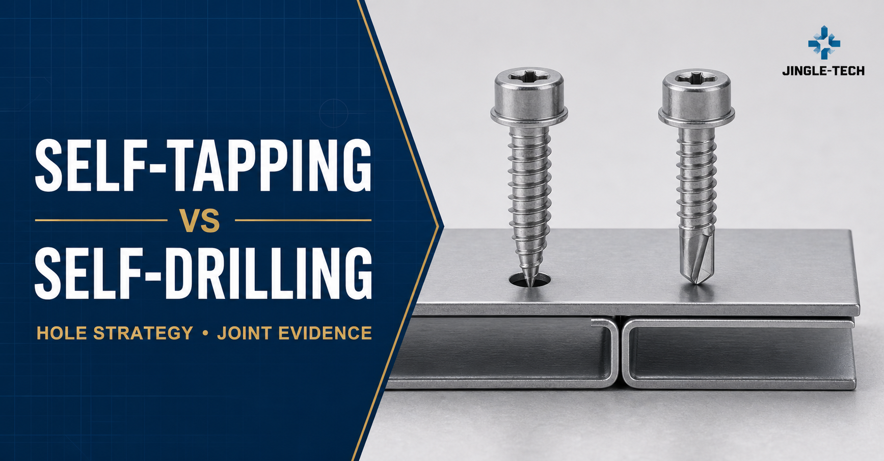
Two sample screws can look almost identical on a buyer’s desk. Both may have coarse threads. Both may have a sharp end. Yet one expects the assembly to provide a suitable starting hole, while the other carries a drill-shaped point intended to make that hole before its threads engage. Mixing them up is not a vocabulary problem; it changes the installation process and the risks inside the joint.
Direct answer: choose a self-tapping screw when the receiving hole is already controlled—predrilled, punched, molded, or otherwise validated—and the screw’s job is to create the mating thread. Consider a self-drilling screw when removing a separate hole-making operation has real value and the exact drill point is documented and tested for the complete material stack. A self-drilling screw still taps. A self-tapping screw is not automatically able to drill.
Neither label tells you which option is stronger, cheaper, faster, or more corrosion resistant. Those answers depend on the joint and the evidence behind the proposed part. Any drilling capacity, driver speed, seating torque, pull-out, or lead-time value must come from the selected product and a controlled review of the intended assembly.
Self-Tapping vs Self-Drilling Screws at a Glance
| Design question | Self-tapping route | Self-drilling route |
|---|---|---|
| Who makes the starting hole? | The part-making or assembly process usually provides a prepared or otherwise suitable hole. | The screw’s defined drill point is intended to make the starting hole during installation. |
| What happens next? | The thread forms or cuts a mating thread in the receiving material. | After drilling, the tapping-screw thread forms or cuts the mating thread. |
| Is a pilot hole relevant? | Often. Its diameter, tolerance, shape, and edge condition can control performance. | Possibly. A locating feature or prepared clearance may still be part of the joint, even when the point drills the retaining member. |
| Best starting use case | A repeatable hole already exists, or hole preparation gives better location and process control. | A one-pass drilling-and-fastening process is desirable and verified for the actual stack. |
| Characteristic failure to watch | Excessive tapping torque, poor thread engagement, stripping, or damage caused by the wrong hole. | Point skating, incomplete drilling, point breakage, premature thread engagement, or sheet separation. |
| What the quote must identify | Thread and point definition, required hole, material, finish, installation guidance, and validation evidence. | The same items plus drill-point designation and supported drill-drive conditions for the stack. |
This comparison belongs to a broader custom-screw topic cluster. Use the custom screw manufacturer guide when the question is how to qualify a production source, and the custom screw cost guide when the question is how tooling, quantity, material, finish, and quality scope shape a quote. This page stays focused on the design choice between the two hole-making routes.
First, Use the Terms Correctly
Self-tapping describes what happens to the mating thread
A tapping screw develops a mating thread as it is driven into an appropriate receiving material and hole. Depending on the design, the thread may form or cut that path. The entry condition still has to be engineered. It might be a drilled pilot, a punched feature in sheet, a molded hole in a polymer component, or another condition supported by the screw design and test evidence.
That is why “self-tapping means no pilot hole” is unreliable advice. A restrictive pilot can make tapping unnecessarily severe; an oversized one can leave too little material for useful engagement. Roundness, burr direction, coating, hardness, and springback also matter. Specify the hole and screw as a pair.
Self-drilling adds a distinct operation before tapping
A self-drilling screw carries a point shaped to remove material and establish the entry hole. Only after that work is complete should the load-carrying thread do its job. ISO makes the relationship explicit in the title of ISO 10666, Drilling screws with tapping screw thread—Mechanical and functional properties. The official wording is more accurate than the common shorthand “one drills, the other taps.” A self-drilling screw is expected to do both, in sequence.
Sequence matters in a layered joint. If the thread engages while the point is still drilling the lower member, the parts may be pushed apart. A seated head can then hide a gap or damaged thread. Point geometry, drilling path, material, support, and tool behavior must work together.
A sharp point in a photograph proves very little
A piercing point, a thread-forming point, and a drill point may all look “sharp” at web-image scale. The head style is not a reliable clue either. A hex washer head, pan head, or countersunk head can be paired with different points and threads. Product titles in a marketplace are particularly weak evidence because naming conventions vary.
For approval, ask for the controlled drawing or recognized designation. It should identify the thread, point, head, drive, material, finish, applicable standard, and claimed functional conditions. A drill-capacity statement without a part revision and test basis remains unverified.
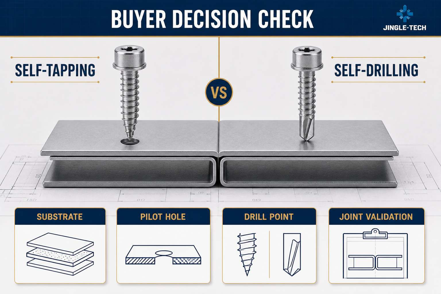
Which Should You Choose? Follow the Joint From Point to Head
1. Name every material the screw will cross
“Metal” is not a specification. Record the grade or relevant material description for every layer, together with hardness or temper when it affects drilling and tapping. A painted cover sheet over a steel bracket is a different problem from aluminum sheet over a stainless support. A polymer cover over a threaded insert is different again. The first layer may guide or damage the point, while a later layer provides the actual retention.
Decide which member carries the thread. If the upper member should provide clearance, its hole must allow pull-down to the lower tapping member. Early engagement in both parts can leave them separated. Successful drilling cannot compensate for an unsuitable retaining member.
2. Describe the stack as it is built, not as a single nominal number
List each thickness range, coating, folded edge, overlap, washer, seal, gap, and tolerance condition. Note the worst credible combination, starting surface, access angle, and part support. A flexible sheet can behave differently from a rigid test coupon.
There is no universal answer to “How thick can a self-drilling screw go?” The useful question is whether the proposed point is documented for the actual material and complete drilling path, then leaves the required thread engagement in the retaining member. Do not apply a thickness claim from one point style, material, or test arrangement to another.
3. Decide whether hole preparation is waste or valuable control
A pilot hole is sometimes waste, but sometimes valuable control. It can locate the joint, prevent skating on a finished surface, manage debris, or give automation a repeatable target. If the part is already punched or molded, its incremental cost may be small.
Favor a self-tapping route when the prepared feature is stable and easy to inspect. Favor self-drilling when the removed operation is significant and drill-drive capability survives normal variation. Compare total installed cost and risk, not screw price alone.
4. Separate penetration from a sound joint
Penetration answers only the first question. The screw must still create useful engagement, pull the parts together, seat without damage, and meet the actual joint requirement. It can drill cleanly and then strip, or clamp in a dry trial but fail after its finish is damaged.
Define “installed correctly” on the drawing or work instruction: head position, washer condition, gap, or another measurable feature. Then name the required retention, shear, clamp, sealing, fatigue, vibration, or service behavior. Engineering should set the method and criteria for this joint.
5. Match the driver to the work the screw must perform
Installation is a sequence of events: starting or drilling, tapping, pulling the parts together, and seating. Each event can create a different torque signature and failure. Record the production driver, bit and fit, available axial force, speed control, clutch or depth control, fixture support, access, and operator or automation method. A poorly fitted bit can damage the recess before the joint reaches clamp; an angled driver can make a capable point wander.
No single speed or torque applies to every candidate. Begin with exact product data and establish a window on representative equipment. Record the failure stage: a point that stalls during drilling needs a different investigation from a screw that spins after seating.
6. Review finish and mating materials as one corrosion system
“Stainless” and “zinc plated” are incomplete requests. The fastener material or coating has to suit the environment, the joined materials, and the mechanical work of installation. Drilling can damage a coating at the point. A bit can mark a head. Dissimilar metals in a conductive environment can create a galvanic concern. A sealing washer adds another material and interface to review.
State the exposure—such as indoor condensation, outdoor weather, salt, cleaning chemicals, or temperature cycling—and identify the governing requirement. ISO 4042:2022, Fasteners—Electroplated coating systems is an authoritative source for electroplated coating systems on steel fasteners within its scope. It is not a blanket durability promise for an assembled product. The selected material, finish, installation damage, joint geometry, and environment still need a specific review.
A Practical Selection Matrix
| Assembly condition | Route worth evaluating first | Reason | Evidence needed before release |
|---|---|---|---|
| A stable punched or drilled hole already exists | Self-tapping | The process already controls location and entry; the screw can be selected around tapping and seating. | Hole tolerance, substrate data, tapping and seating window, and joint test. |
| Suitable sheet or section stack with no prepared hole | Self-drilling | One-pass installation may remove a separate hole-making step. | Point identity, supported drill capacity for the full stack, drill-drive trial, engagement, and joint test. |
| Cosmetic or curved starting surface | Compare both | A pilot may improve location and protect the finish; a self-drilling design may still work with proper support and validation. | Start consistency, surface damage, swarf control, alignment, and final appearance. |
| Multiple layers with variable overlap or gaps | Compare both cautiously | Point clearance and early thread engagement can change across the stack. | Worst-case stack trials, pull-down observation, retained engagement, and required mechanical tests. |
| Polymer or composite is a functional member | Substrate-specific self-tapping or another fastening system | Heat, cracking, fiber damage, creep, and boss geometry may control the design. | Material-specific thread and pilot guidance plus conditioning and assembly tests. |
| Field retrofit into an uncertain substrate | Pause and identify the joint first | A more aggressive point does not resolve unknown material, hidden layers, or required retention. | Verified substrate, hazard review, representative mock-up, and approved work instruction. |
Cost and Lead Time: Compare the Process, Not Just the Screw
Self-drilling may remove an operation, but that is not the whole cost equation
When a buyer asks which costs more, the honest answer is “quote the defined alternatives.” Self-drilling may save hole-making labor and handling, yet require a specific point, tooling, material route, or added validation. Self-tapping may have a lower piece price while relying on a costly prepared-hole process.
Normalize drawing revision, quantities, material, finish, inspection, packaging, delivery terms, and samples. Add hole preparation, bits, tool wear, cycle variation, rework, damaged parts, and line stoppage. The lowest unit price may not produce the lower-cost joint.
Lead time begins with specification maturity
A catalog configuration and a custom point/head/thread combination follow different schedules. Tooling, raw material, heat treatment, coating, test scope, sample approval, packaging, and production capacity can all affect timing. None of those variables can be converted into a reliable delivery promise in a generic article.
Ask each bidder to separate drawing review, tooling if needed, sample timing, approval dependencies, production lead time, and transit. State when your team will return sample feedback. This makes two quotations comparable and exposes a common hidden delay: an RFQ that changes after the supplier has already planned the process.
Hypothetical Design Review: A Coated Panel Over a Steel Bracket
This scenario is hypothetical. It demonstrates the reasoning process and does not describe a JINGLEFIX product, customer, test result, or manufacturing capability.
An enclosure designer needs to fasten a coated outer panel to an internal steel bracket. The panel is visible to the end user. The bracket is intended to retain the thread. Installers have one-sided access, and the joint must remain closed without marking the finish.
The first proposal is self-drilling because it appears to remove a hole-making step. The review asks whether the point clears both layers before the thread engages, whether it damages the coating, where swarf falls, whether the head protects the panel, and whether the driver stays square.
The second proposal uses a self-tapping screw, panel clearance, and a controlled bracket hole. It retains hole preparation but may improve location and pull-down. The holes must stay aligned, and tapping must not distort or strip the bracket.
Both candidates go into representative coated assemblies selected by engineering. The trial records starting, drilling, thread engagement, pull-down, seating, surface condition, and the required joint property. The winner meets the technical and commercial criteria, not the more convenient name.
Failure Symptoms Are Clues, Not Specifications
| What you observe | Likely area to investigate | Next controlled check |
|---|---|---|
| The point wanders before starting | Point-to-surface match, alignment, support, finish, or need for a locating feature. | Repeat with controlled alignment and representative finish; compare a defined pilot route. |
| The screw stalls before the thread reaches the lower member | Drill-point capacity, substrate hardness, stack variation, tool input, flute condition. | Confirm point revision and supported conditions; inspect the stage at which drilling stopped. |
| The sheets stay apart | Premature thread engagement, missing clearance, point length, part fit, or insufficient pull-down. | Section or disassemble the joint and observe engagement timing in a transparent or staged trial where practical. |
| The screw spins after appearing seated | Stripped receiving thread, oversized pilot, soft or insufficient retaining material, unsuitable tool setting. | Inspect the hole and thread, review the installation trace if available, and test a controlled hole range. |
| The drive recess or head is damaged | Bit fit, alignment, installation window, head/drive choice, or excessive resistance earlier in the sequence. | Verify bit designation and screw drawing; determine whether damage began during drilling, tapping, or seating. |
| The screw breaks | Drilling or tapping demand, screw properties, heat treatment, geometry, tool conditions, or material mismatch. | Retain the fracture and lot identity; stop substituting settings until the failure stage and material evidence are reviewed. |
| Corrosion appears around the joint | Finish selection, coating damage, dissimilar metals, moisture trap, washer or seal compatibility. | Review the full corrosion system and test method, not only the screw’s finish name. |
Run a Controlled Trial Before the Purchase Order
Make the trial repeatable before trying to make it fast
Most disputed screw trials have the same weakness: the team remembers the screw but not the conditions around it. Tag the candidate by drawing revision and lot. Keep the actual bit and driver with the record, and describe the material stack as it was tested—not merely as it appears on the product drawing. Production parts are preferable. When only coupons are available, write down the missing features, such as a formed edge, flexible panel, coating, or restricted access.
For an A/B decision, change the hole-making route and hold the other influential conditions steady. If the operator, bit, stack, and tool setting all move at once, a quicker drive proves very little. The trial is ready when another technician could reproduce it without asking what the first team “probably used.”
Watch the transition points, not just the seated head
Stand beside the first installations and follow the work in order. Does the point establish its location cleanly? On a drilling screw, does breakthrough occur before the threads begin pulling on the stack? Next, watch the parts close and the head come to its intended seat. That short sequence usually tells an experienced observer more than a final photograph.
The record sheet should capture evidence that changes a decision. Swarf matters when it remains inside an enclosure or blocks seating; a scuff in the coating matters when the finish is part of the corrosion system. Wobble is useful to note when it points to alignment, bit fit, or point geometry. Avoid turning every run into the same long checklist regardless of the joint.
An instrumented torque-angle or torque-time trace is valuable only when the team can relate a feature on the curve to drilling, tapping, pull-down, or seating. It can expose variation that the eye misses. It cannot show whether a hidden thread has been torn out or whether a sealing washer is sitting correctly, so open or section selected joints as the risk requires.
Test the failure the product cannot tolerate
A housing screw and a structural panel screw do not need the same evidence. Begin with the consequence of joint failure, then select the relevant mechanical, sealing, vibration, service, or environmental test. Write the fixture, conditioning, loading direction, sample logic, and acceptance rule before results are visible. One convenient pull-out result should never be promoted into a universal load claim.
ASTM C1513-24, Standard Specification for Steel Tapping Screws for Cold-Formed Steel Framing Connections is a useful example of application-specific control. Its scope includes self-drilling and self-piercing tapping screws for cold-formed steel framing connections and identifies functional evaluations such as torsional strength, drill-drive performance, and drill capacity. Its requirements should not be transferred to an unrelated joint simply because both use sheet metal.
Release the way of installing it, not only the part number
A released screw can still fail on the line if the approved bit, hole condition, or driver window is lost. Put those items next to the screw revision and joint drawing in the work instruction. Also give production a practical reaction: stop and segregate after a broken point; route a stripped hole through an approved repair decision; do not hide an incomplete seat with extra driver time. Supplier change notification should cover the characteristics the review found functional, which may include the point, thread, material, heat treatment, coating, or source.
Build an RFQ That Produces Comparable Answers
A high-conversion screw RFQ is also a high-quality engineering record. It reduces the supplier’s need to guess and gives procurement a basis for comparing price, lead time, and quality evidence. Include:
- Joint purpose: what the fastener must clamp, retain, seal, or allow to be serviced, and which member carries the thread.
- Complete stack: every material, grade or relevant specification, hardness or temper when applicable, thickness range, coating, gap, overlap, washer, and seal.
- Hole strategy: no prepared hole, pilot, punched or molded hole, upper clearance, existing field hole, and the applicable tolerances and edge condition.
- Screw definition: proposed diameter and length, thread, point, head, drive, under-head features, material, heat treatment, finish, and drawing revision. Mark undecided items for review.
- Installation: tool and bit, direction and access, manual or automated process, fixture support, and available controls.
- Service conditions: load modes, clamp or sealing requirement, environment, mating metals, temperature, chemicals, service life, and removal expectations.
- Quality evidence: applicable standards, inspection reports, material and finish documentation, functional test scope, lot traceability, and change-control expectations.
- Commercial basis: prototype, order, and forecast quantities; packaging and labeling; delivery destination; requested sample timing; production timing; and quotation validity.
- Confidentiality: the approved channel for drawings, required confidentiality terms, limits on subcontractor access, document return or retention, and who may approve changes.
For product-family context before sending the RFQ, review the available fastener categories. Treat any category page as orientation only; the controlled drawing, quoted specification, and validated joint remain the purchasing basis.
Frequently Asked Questions
When a buyer says “self-tapping,” does that include self-drilling?
In functional terms, yes—with an important qualifier. A self-drilling screw first makes the entry hole and then its tapping-screw thread develops the mating thread. ISO 10666 reflects that relationship in the phrase “drilling screws with tapping screw thread.” On a drawing or purchase order, however, “self-tapping” alone is too broad; identify the drilling point and the supported application. The short conclusion is that self-drilling adds a function, not a substitute name.
Should the drawing call out a pilot hole for a self-tapping screw?
Start with the proposed point and receiving material. If a punched or molded hole is already controlling location, call it out and validate its usable range. Some point-and-substrate combinations are designed to start without a separate pilot, but that absence is still an entry condition the assembly must prove. On a cosmetic surface or an automated line, a small locating feature may be worthwhile even when penetration is possible without it. In short: specify the hole strategy explicitly; never leave it to the family name.
Can a self-drilling joint still use a locating hole?
Yes. For example, the upper panel may use a clearance or locating feature while the drill point makes its way into the retaining member. That arrangement can improve alignment without turning the screw into a conventional prepared-hole design. What matters is the actual sequence through the stack, so test the screw and both hole conditions together.
For a metal assembly, where should the comparison start?
Look first at how the hole is made today. If a stamped part arrives with a stable, inspectable hole, self-tapping may give the simpler and more repeatable job. If an installer faces an unperforated stack and a documented drill point covers it, self-drilling may remove a genuine operation. Only then compare pull-down, retained engagement, finish damage, tooling, and total installed cost. “Metal” does not choose the screw; the stack and the process do.
Which should I choose for thicker metal?
Do not choose by thickness alone. Ask whether the exact point is documented for the material and complete drilling path and whether the retained thread and joint meet the requirement. If the point is not supported for the stack, consider a prepared-hole route or another fastening method.
A self-drilling screw stops or breaks—what should be checked first?
Do not begin by adding more driver power. Keep the failed screw and look at where the operation ended. A point that never cleared the lower sheet sends the review toward the supported drilling path, material condition, alignment, and point identity. A fracture after thread engagement moves attention to tapping demand, pull-down, and the screw’s documented properties. Compare the event with the lot record before changing settings. Diagnose the stage first; adjust the process second.
The self-tapping screw spins in the hole. What does that tell you?
Spinning is a late symptom, not the root cause. Remove the joint without destroying the evidence and inspect the receiving hole: was a thread formed, was it torn out at seating, or was there never enough material to engage? Then compare the actual pilot and substrate with the released condition. A larger screw may be an approved repair in some products, but it is not an automatic cure. Verify the hole-and-thread pair before blaming final torque.
Which route costs more once it reaches the production line?
Quote the two complete routes. A self-drilling screw may carry a higher piece cost yet eliminate a drilling station, handling step, or alignment problem. A self-tapping screw may be inexpensive while the prepared hole and its inspection absorb more money. Tool wear, damaged panels, stripped-hole repairs, and lost cycle time can reverse an apparently obvious comparison. Piece price is the wrong level for the final decision.
What should a realistic lead-time answer contain?
First establish whether the quote uses an existing configuration or a new drawing. From there, ask the supplier to show the milestones that matter for this part, including any tooling or sample approval, rather than returning one unexplained number. Buyer review time can be a real dependency, especially if the specification is still moving. A credible answer states its assumptions and separates sample timing from repeat-production timing.
Which quality records are useful, rather than merely impressive?
Begin with the failure the joint cannot tolerate. If drilling consistency is critical, the functional evidence and lot identity deserve attention; if finish is critical, the coating requirement and inspection record move forward. The approved drawing and revision should anchor either package. A small set of relevant, traceable records is better than a thick certificate folder that never addresses the joint.
How much drawing detail belongs in an RFQ, and how should it be protected?
Buyers often choose between two bad extremes: sending the entire product history to an unqualified bidder or withholding so much that the quote becomes guesswork. A staged release is more practical. Initial screening can use the functional envelope or a redacted view; after the agreed confidentiality terms are in place, issue the controlled revision needed for process and price review. Record who receives it and whether subcontractor access is allowed. The governing terms should be set by qualified legal or commercial personnel—this is process guidance, not legal advice.
Can one screw be released for metal, plastic, and wood?
Only if each application earns its own evidence. A thread that forms cleanly in sheet metal may split wood or overstress a plastic boss; a point that helps in timber may offer no controlled drilling function in metal. There are cases where one catalog part works across several specified materials, but that is a product-specific result, not a family rule. Treat the hole, installation window, and acceptance test as separate releases for each substrate.
Primary Standards Behind the Decision
Standards have defined scopes. They help establish terminology, dimensions, properties, and test expectations, but they do not approve a screw for every assembly. Check the edition and contractual requirement that applies to the project.
- ISO 1478:1999, Tapping screws thread — the ISO reference for tapping-screw thread characteristics; ISO lists this edition as current following its 2024 confirmation.
- ISO 10666:1999, Drilling screws with tapping screw thread—Mechanical and functional properties — directly relevant to the combined drilling-and-tapping function; ISO lists this edition as current following its 2024 confirmation.
- ISO 15480:2019, Fasteners—Hexagon washer head drilling screws with tapping screw thread — a dimensional product standard for one defined drilling-screw form, not every head, point, or size.
- ASTM C1513-24, Steel Tapping Screws for Cold-Formed Steel Framing Connections — an application-specific primary source that illustrates how drill-drive and mechanical requirements are tied to scope.
Make the Decision Traceable
The choice is complete only when another engineer or buyer can follow it. The record should show who makes the hole, which member retains the thread, why the point and thread suit the stack, how the head creates the intended clamp, which finish suits the environment, how the production tool is controlled, and what tests release the joint. That is more durable than a rule such as “use self-drilling for metal.”
Bring the drawing, stack-up, hole strategy, service conditions, required quality evidence, quantities, and timing into one RFQ. Then request screw samples and a bulk quote for the defined assembly rather than for a generic screw name.