Screw Head and Drive Types for OEM Assembly: A Buyer’s Selection Guide
Quick answer: select screw head and drive types by starting with the joint and the assembly process—not with a familiar catalogue name. The head must fit the available envelope, seat on the intended surface, transfer clamp load without unacceptable embedding or distortion, and meet flushness, appearance, safety and service requirements. The drive must accept the specified bit or wrench, provide adequate engagement in the real access direction, survive the proposed installation strategy, and support manual or automated handling.A defensible RFQ therefore identifies the adopted product standard and edition, head form, drive/recess form and size, mating tool, seating geometry, installation window, finish condition, inspection method and change-control rules. A supplier should return exceptions and validation evidence against that baseline rather than silently substituting a “similar” head or recess.
A screw can have a conforming thread and still fail the assembly objective. The head may collide with a wall before the bit reaches full depth. A countersunk head may contact only at one edge because the mating countersink is wrong. A broad bearing face may mark a cosmetic panel. A shallow recess may pass a visual check yet wobble in the production bit. An internal drive that works on a bench may be inaccessible after the wiring harness is fitted.These are interface failures, not simply “bad screw” failures.
Procurement also sees the commercial consequences. If head height, recess identity or seating geometry is ambiguous, bidders may price different products under the same description. Samples become difficult to compare, inspection reports measure different features, and a later substitution can alter tooling or line behavior. The buyer’s best protection is a requirement chain that links application need to part definition, validation and receiving evidence.
Send your drawing for a head-and-drive requirement review
1. Start with the assembly function, then name the head and drive
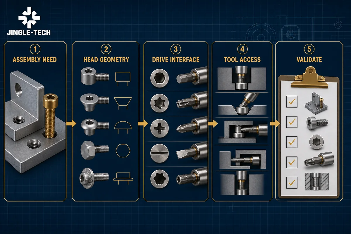
The head performs several jobs at once. It presents a surface for the tool, creates or supports a bearing interface, limits how far the screw enters, occupies a three-dimensional envelope and remains visible—or deliberately disappears—after assembly. The drive transmits installation and removal input, but it also affects bit alignment, axial access, debris sensitivity, inspection and servicing. Treating these as independent catalogue fields loses the interactions that matter.
Begin with a short “assembly identity statement.” It should say what is clamped, what surface supports the head, how the tool approaches, whether the joint is permanent or serviceable, what appearance and safety constraints apply, and what event defines successful installation. Add the screw thread, material and finish only after the functional statement is clear. This order prevents a legacy part number from deciding the design before the joint has been reviewed.
For example, “flush screw for a panel” is incomplete. Flush to which datum? Is the panel ductile, brittle, coated or laminated? Is the countersink machined, molded or stamped? May the head sit slightly below the outer skin? Does the driver approach normal to the surface? Will the screw be removed during field service? Is the panel thickness sufficient for the selected countersink without creating a knife edge? Each answer can change the acceptable head and drive combination.
| Decision layer | Buyer question | Controlled output | Failure if skipped |
|---|---|---|---|
| Joint function | What must be clamped, located, retained, sealed or serviced? | Named functional requirements and misuse boundaries. | A geometrically fitting screw that does not support the joint. |
| Seating interface | What surface carries the head load and what movement is allowed? | Bearing face, countersink or washer/collar definition. | Edge contact, embedding, panel damage or loss of clamp. |
| Envelope and access | What may the head and tool occupy during assembly and service? | Clearance model, approach angle and obstruction sequence. | Partial engagement, collision or impossible removal. |
| Installation | Manual, powered or automated; what control strategy and reaction exist? | Tool/bit, program concept and validation plan. | Damaged recess, unstable cycle or false acceptance. |
| Lifecycle | Must it look clean, resist casual access, or be removed repeatedly? | Appearance, security, service and tool-control requirements. | Wrong service tool, cosmetic rejection or access vulnerability. |
| Definition and evidence | Which standard, edition, dimensions, gauges and tests establish acceptance? | Released drawing, inspection plan and supplier return. | “Equivalent” products that cannot be compared. |
A useful team review includes design engineering, manufacturing engineering, quality, service and procurement. Design owns the joint intent. Manufacturing engineering owns access and process feasibility. Quality helps convert the definition into measurable acceptance. Service confirms removal and replacement conditions. Procurement ensures quotations disclose what each bidder actually proposes. No single catalogue comparison can replace those decisions.
2. Compare head geometry by seating behavior—not by profile alone
Common names such as pan, cheese, button, socket head, countersunk, raised countersunk, flange and hex head are useful search terms, but they are not complete definitions. A head family may appear in several product standards, with different thread ranges, product grades, drive options, bearing details, head heights or loadability statements. A buyer should name the selected product standard and edition—or fully dimension a special head—rather than assume every supplier uses the same catalogue geometry.
Non-countersunk heads
A pan-style head offers a rounded outer profile and a flat underside in many standardized products. It may suit a general assembly where projection is acceptable and a conventional bearing surface exists. A cheese or cylindrical style can offer a different height-to-diameter envelope. A socket head cap screw provides an internal drive within a taller cylindrical head; the official page for ISO 4762:2004 describes one metric coarse-thread, product-grade-A family, not every internal-hex screw. A button head reduces profile but may also change drive depth, bearing geometry and loadability. The current ISO catalogue includes product-specific button-head parts, including ISO 7380-3:2026 for a defined range of hexalobular-socket button heads with reduced loadability. That word “reduced” is an engineering boundary, not a marketing footnote.
Countersunk and raised-countersunk heads
A countersunk head can support a flush or recessed exterior, but it turns the mating countersink into part of the joint. Head angle, countersink angle, diameter, depth, concentricity, panel thickness and surface condition interact. The official scope for ISO 7721:1983, confirmed current in 2024, concerns countersunk-head configuration and a recommended gauging method for products in its stated size range. ISO 15065:2005 covers countersinks used with heads conforming to ISO 7721 and lists applicable product families in its scope. Neither reference proves that a chosen head is compatible with a buyer’s actual panel without assembly validation.
Product standards also expose non-interchangeability that a generic name hides. ISO 14581:2022 covers a defined hexalobular-socket countersunk flat-head family with reduced loadability and cautions about alignment with the countersink bearing surface. The ISO page contrasts it with high-head products under ISO 14582 and states that the two are not interchangeable because head heights differ. Likewise, ISO 10642:2026 is a current product standard for a specified hexagon-socket countersunk family with reduced loadability. The sourcing lesson is simple: “flat head” or “countersunk socket screw” is not enough.
| Head family | Potential reason to evaluate | Interface questions | Do not assume |
|---|---|---|---|
| Pan | General raised-head assembly with a flat bearing face. | Head diameter/height, edge clearance, bearing material and recess depth. | That all pan heads share one contour or drive. |
| Cheese/cylindrical | A narrower or taller envelope under a defined product standard. | Side clearance, snagging, tool access and head strength. | That the name fixes height-to-diameter proportion. |
| Socket head cap | Internal drive with a defined cylindrical-head family. | Head-height clearance, counterbore, key entry and recess condition. | That any internal hex has the same product properties. |
| Button | Low rounded profile or appearance objective. | Reduced-loadability statement, recess depth, bearing area and access. | That low profile preserves cap-screw capacity. |
| Countersunk flat | Flush or below-surface objective. | Included angle, depth, panel thickness, alignment and loadability. | That “flush” is achieved without a mating specification. |
| Raised countersunk | A countersunk bearing interface with a deliberately raised crown. | Visible projection, recess depth and mating countersink. | That it meets a flat-flush cosmetic requirement. |
| Flange or washer head | Broader bearing interface or integrated geometry. | Panel stress, flange flatness, edge clearance and coating damage. | That broader bearing always improves the complete joint. |
| External hex | External wrenching where radial tool access is available. | Socket envelope, swing/access, corners, washer or flange interface. | That it fits a confined pocket better than an internal drive. |
This table is a screening tool, not a ranking. The best candidate is the one that supports the defined joint and can be made, installed, inspected and serviced under controlled conditions. A buyer should carry at least two candidates into an early design review when the seating or access boundary is still uncertain.
3. Design the seating surface and clamp-load path together
The head’s underside transfers load into the clamped component. That simple statement has important consequences.The material beneath the head may be hard steel, soft aluminum, molded polymer, a coated sheet, a composite stack or a fragile finish. Contact geometry changes local bearing pressure and the way the joint settles. A wider face may distribute load, but it may also cross an edge, sit on a radius or bridge an uneven surface. A smaller face may fit the envelope but create unacceptable local deformation. Engineering must establish the allowable condition.
For a flat-bearing head, define the bearing datum and check whether the underhead radius or runout collides with the hole edge. If a washer is required, define its dimensions, hardness/material, finish and whether it is loose, captive or preassembled. Do not treat “with washer” as an inspection detail: the washer can alter clamp transfer, embedment, stack height, tool access, loosening behavior and packaging.
For a countersunk head, the cone is the bearing interface. If the head and countersink angles, depths or centers do not match, contact can concentrate near the top or bottom of the cone. The screw may appear flush before the desired clamp state exists, or it may stand proud even though the driver has reached a control limit. In a thin sheet, the countersink may remove too much supporting material. In a molded seat, draft, sink and tool wear may affect contact. These risks require a mating-part definition and an assembly study, not a screw-only inspection.
| Interface | Drawing inputs | Validation observation | Possible reaction if unsuitable |
|---|---|---|---|
| Flat bearing face | Head diameter, underside geometry, hole edge, surface flatness. | Contact pattern, indentation, tilt and post-install settling. | Revise bearing area, washer, seat or joint design. |
| Countersunk cone | Head/countersink geometry, depth datum, panel thickness and concentricity. | Flushness, contact band, panel distortion and alignment. | Correct the mating countersink, head family or acceptance rule. |
| Washer or collar | Outside/inside geometry, thickness, material, finish and retention. | Rotation, edge bridging, coating scuff and embedment. | Change component stack or control washer identity. |
| Soft or cosmetic surface | Allowable mark, deformation, pressure and protective layer. | Visible ring, paint damage, creep and relaxation. | Add interface protection or redesign the load path. |
| Curved or uneven seat | Allowed angular mismatch and support geometry. | One-sided contact, head bending and unstable final position. | Provide a formed boss, seat, washer or other engineered interface. |
Clamp load should be validated at joint level when it matters. ISO 16047:2005 specifies conditions for torque/clamp-force tests within a stated scope and exclusions. It does not turn a generic torque value into a universal assembly setting, and it excludes several fastener categories. If the buyer uses that standard, the actual fastener, mating thread, bearing surfaces, lubrication/finish condition and test setup must be reviewed against its scope and the contract.
4. Model the tool envelope before freezing the drive
Tool access is more than an unobstructed line to the screw center. A driver bit or key needs engagement depth, a holder, a spindle or handpiece, and room for the operator or automation. An external hex needs a socket wall and possibly radial swing. A right-angle tool changes the envelope and reaction. Fixtures, cables, guards and nearby fasteners can obstruct the approach during one assembly stage even if the final CAD view looks clear.
Create three envelopes: the screw head as installed, the tool at full engagement, and the tool as it approaches or leaves. Then test the real assembly sequence. A component installed later may block service access. A recessed pocket may accept a bit but not the holder. A deep counterbore may cause the holder to rub before the bit bottoms in the recess. If a drive needs strong axial seating, the workstation must also support the required reaction without damaging the assembly or increasing ergonomic risk.
Access angle deserves a defined limit. “Slight angle allowed” is not measurable.If non-normal entry is unavoidable, engineering should test the chosen head/drive/bit system across the expected tolerance envelope and tool wear condition. The result may be a fixture change, a different drive, a different head height, a longer bit, a revised sequence or a design change that relocates the fastener.
| Envelope item | Check in CAD | Check on physical build | Record for RFQ |
|---|---|---|---|
| Axial approach | Bit, holder and spindle path. | Fixture, hand clearance and component sequence. | Permitted approach direction/angle. |
| Radial clearance | Socket outside diameter or key/handle sweep. | Obstructions and operator motion. | Maximum tool envelope. |
| Engagement depth | Head pocket, counterbore and bit penetration. | Bottoming, debris, coating and holder interference. | Bit form/size and engagement criterion. |
| Reaction path | Where installation forces and moments travel. | Part movement, fixture deflection and ergonomics. | Fixture state and support assumptions. |
| Service state | Access after all surrounding parts are installed. | Corrosion, contamination, wear and visibility. | Approved service tool and replacement rule. |
Ask for an RFQ checklist that includes tool access and seating
5. Select the drive as a screw–bit–tool interface
A drive name is shorthand for an interface, not a promise of assembly performance. The recess or external feature, mating bit or wrench, installation tool, operator/robot motion, axial force, speed, control strategy and wear state work together. Comparing shapes in isolation encourages broad claims such as “higher torque” or “no cam-out.” Those claims are unsafe without a defined size, product, material, recess quality, bit, joint and test condition.
Slotted and cross-recessed drives
A slot can support simple tooling and a particular appearance, but the open geometry and centering behavior require consideration in the actual process. Cross recesses must be identified by form, not merely called “cross-head.” The official scope of ISO 4757:1983, confirmed current in 2023, defines H and Z recess types, dimensions and penetration gauging.The corresponding tool interface matters: ISO 8764-1:2004, confirmed current in 2024, identifies PH tips for H recesses and PZ tips for Z recesses. This is why an RFQ that says only “Phillips/Pozidriv acceptable” invites mismatch rather than flexibility.
Internal hex and hexalobular drives
Internal hex and hexalobular features can support compact axial tooling, but engagement depends on the specified recess geometry, bit size, depth, corner or contour condition, contamination and alignment. The official page for ISO 10664:2014 states that it defines the shape, basic dimensions and gauging method for a hexalobular internal driving feature. It also explicitly says the document is intended to provide inspection details and is not a manufacturing standard. A buyer therefore still needs an applicable product standard or a complete part definition.
External hex and controlled-access drives
An external hex shifts engagement outside the head and needs radial socket clearance. It can be suitable in many assemblies but may be poor in a narrow pocket or under a cosmetic cover.Controlled-access or tamper-resistant features should be selected from a threat and service model: who must be discouraged, who must retain authorized access, how tools are controlled, whether emergency removal exists and how field damage is handled. “Security screw” is not a complete security requirement, and unusual drives are not automatically secure.
| Drive family | Potential reason to evaluate | Validation focus | RFQ control |
|---|---|---|---|
| Slot | Simple feature, legacy fit or defined appearance. | Centering, blade fit, side escape, surface marking and automation. | Slot geometry, blade/tool and allowable visual condition. |
| Cross recess H | Defined H recess with matching PH tool under adopted standards. | Penetration, wobble, axial seating, bit wear and finish. | H form, recess size, product standard and PH bit. |
| Cross recess Z | Defined Z recess with matching PZ tool under adopted standards. | Same system checks plus prevention of H/Z tool mixing. | Z form, recess size, product standard and PZ bit. |
| Internal hex | Axial access and a compact internal wrenching feature. | Across-flats fit, depth, corner condition, key/bit insertion and stripping mode. | Product standard, socket size and mating tool. |
| Hexalobular internal | A defined lobed interface for the selected product and tool system. | Contour gauge, penetration, wobble, debris, bit life and automation behavior. | Feature size, product standard, gauge and bit definition. |
| External hex | External socket or wrench access. | Across-flats/corners, socket clearance, rounding and tool reaction. | Head standard, wrench size and socket envelope. |
| Controlled-access feature | Defined deterrence or tool-control objective. | Threat model, authorized removal, supply continuity and damage response. | Exact interface, authorized tool, ownership/IP and service plan. |
The selection record should explain why a drive remains in the shortlist and which test can eliminate it. That is more useful than a generic advantage list. If a cross recess and a hexalobular recess both fit, build production-intent samples, use the intended bits and equipment, challenge alignment and wear, and evaluate the resulting installation data and damage modes. The winning interface is the one that meets the buyer’s verified requirements.
6. Add automation requirements before requesting production samples
Automated assembly expands the interface beyond the screwdriver. Screws must be stored, separated, oriented, transported, presented, engaged and driven. Head geometry can influence feeding and presentation; the drive can influence bit pickup or engagement; finish and oil can affect friction and sensor behavior; dimensional variation can influence escapements and nests. A screw that installs reliably by hand is not automatically ready for a feeder and robot.
Define the automation architecture without forcing the fastener supplier to guess proprietary line details. State whether screws are bowl-fed, step-fed, blow-fed, tray-presented, manually picked or supplied through another system. Identify orientation features, maximum envelope, permitted contact surfaces, cleanliness restrictions and allowable tangling or nesting risks. Explain whether the tool uses vacuum, magnetism, mechanical retention or no pickup aid. If magnetic response matters, it belongs in the controlled requirement set, not in a late email.
Installation monitoring must be linked to physical acceptance. A torque trace can show a process signature, but it does not by itself prove clamp load, seating or recess integrity. An angle threshold can help detect missing engagement, yet it may be affected by joint variation. Vision can confirm presence or head position while missing an internal drive defect. Combine sensors only after deciding which failure each channel is intended to detect and what containment follows an alarm.
| Stage | Challenge condition | Recorded evidence | Decision question |
|---|---|---|---|
| Presentation | Lot variation, normal contamination and allowed packaging condition. | Misorientation, nesting, jams and surface damage by defined method. | Can the head family be presented within line requirements? |
| Pickup and approach | Expected positional/angular variation and worn retention element. | Drops, false pickups, collisions and entry angle. | Does the tool reach and hold the screw consistently? |
| Drive engagement | Recess variation, finish, representative debris and bit wear. | Penetration, wobble, engagement delay and damaged recesses. | Is the screw–bit system robust across allowed variation? |
| Tightening | Joint stack, finish condition, speed and programmed strategy. | Tool trace, final position, joint evidence and failure mode. | Does control separate acceptable joints from named faults? |
| Removal/service | Aged or conditioned assemblies as required by the application. | Tool access, recess condition, removal signature and collateral damage. | Can authorized service remove the screw safely? |
7. Balance appearance, safety, security and service
Visible screws affect the product experience. A rounded head can look deliberate on one enclosure and unfinished on another. A countersunk head can support a smooth surface, yet a proud edge may become a snag or cosmetic defect. Tool contact can mark a plated or painted head. Recess fill, burrs and inconsistent orientation may be visually unacceptable even when the screw can be installed. If appearance matters, the drawing or appearance standard should define viewing condition, protected zones and permissible marks instead of relying on “cosmetic quality.”
Safety requirements may favor a flush surface, discourage sharp projections or require a head that cannot be casually loosened. Security is a different question. A controlled-access drive can deter an opportunistic user, but the real control system includes tool availability, authorized maintenance, replacement parts, emergency access and evidence of tampering.Procurement should ask who owns any proprietary interface, whether tools remain available through the product life and what happens if the drive supplier changes the geometry or exits the market.
Serviceability can conflict with deterrence and low profile. A small, shallow recess may satisfy the industrial designer while giving a technician little engagement after the head is contaminated or painted. Repeated removal can change the recess and bearing surface. If reuse is permitted, define the acceptance decision for the screw and the mating thread after each service event. If reuse is prohibited, define a replacement kit and ensure the bill of materials and service documentation control the exact head and drive.
| Lifecycle need | Define before sourcing | Validation evidence | Supply-chain control |
|---|---|---|---|
| Cosmetic surface | Color/finish, viewing zone, proud/flush condition and tool-mark limit. | Approved visual master or documented criterion under stated lighting. | Packaging, handling and bit condition. |
| User safety | Allowable projection, edge condition and access restriction. | Assembly-state inspection and applicable product safety review. | No unapproved head substitution. |
| Access deterrence | Threat actor, deterrence objective and authorized tool custody. | Defined misuse challenge and service trial. | Tool and replacement availability through product life. |
| Routine service | Access state, cycles, environment and replace/reuse rule. | Removal/reinstallation trial with representative conditioning. | Service kit controls exact interface and approved tool. |
| End-of-life disassembly | Required separation, tool access and damage tolerance. | Disassembly sequence review. | Long-term tool and documentation availability. |
8. Put a complete head-and-drive callout on the drawing and RFQ
A good callout closes the gap between a design concept and a purchasable, inspectable part.For a standard product, identify the standards organization, document number, edition required by the contract, product designation and any permitted options. Add the thread designation, nominal length convention, material/property requirements, finish, cleanliness, marking, packaging and inspection documents. If the head or drive is special, control its geometry and the mating gauge or measurement method rather than combining a standard name with conflicting custom dimensions.
Standards must be applied within scope. ASME B18.6.3-2024 is titled for machine screws, tapping screws and metallic drive screws in inch series and is on stabilized maintenance. It is not a universal metric head catalogue. Conversely, a metric ISO product standard may have a limited thread range, product grade, material/property class or loadability statement. The buyer should acquire and review the full adopted document; an abstract or title is not enough to release production.
Avoid dual callouts that create two masters. “Per standard X, except as shown” can work only if every exception is explicit and the remaining standard requirements are understood. “Equivalent to X” is weaker: equivalent in head outline, recess, material, performance, finish, interchangeability or inspection? If alternates are acceptable, list the characteristics that must remain identical, the ones that may differ and who approves the supplier’s proposed deviation.
| Callout field | What to state | Supplier must return | Common ambiguity |
|---|---|---|---|
| Product identity | Part number, revision, standard and contract edition. | Exact offered designation and exceptions. | A generic catalogue family returned as “equivalent.” |
| Head | Standard head form or fully controlled special geometry. | Head dimensions, product-grade basis and loadability note. | Name used without dimensional source. |
| Drive/recess | Feature form, size, governing document, gauge and mating bit/tool. | Proposed feature and inspection method. | “Cross,” “star” or “Allen” used as complete geometry. |
| Thread/length | System, size, pitch/TPI, tolerance/class, length and datum convention. | Acknowledged thread and measurement basis. | Countersunk versus non-countersunk length convention ignored. |
| Material/properties | Material system, condition and applicable property specification. | Proposed grade/class and document route. | Material name treated as full mechanical definition. |
| Finish | Coating system, appearance, thickness/functional requirements and post-finish acceptance. | Process proposal, exceptions and test/document plan. | Color alone used as coating specification. |
| Assembly and inspection | Mating tool, validation state, CTQs, methods, sampling and document type. | Feasibility, proposed controls and evidence index. | “Fit and function” with no test or decision rule. |
9. Check how material, property requirements and finish change the head/drive decision
Material and property-class selection cannot be inferred from head shape. The official scope for ISO 898-1:2013 covers mechanical and physical properties of specified carbon- and alloy-steel metric fasteners under defined conditions and exclusions; the ISO page currently marks it “to be revised.” It also notes geometry-related limits for certain head forms.ISO 3506-1:2020 applies to defined stainless-steel bolts, screws and studs and expressly excludes several functional properties from its scope. Neither document makes a property class a complete joint-performance specification.
Head geometry removes or redistributes material around the drive. A deep internal feature in a low head leaves a different section from the same feature in a tall head. That is why some ISO button and countersunk product standards explicitly identify reduced loadability. Buyers should not combine a desired low profile, a deep drive and a high property designation without checking whether a relevant standardized product exists and whether the head can support the required behavior.
Finishes also affect the interface. Coating may change recess fill, edge definition, head dimensions, friction, appearance and tool engagement. Electroplating on high-strength steel requires appropriate review of hydrogen-embrittlement risk. The current official ISO listing is ISO 4042:2022 together with Amendment 1:2026 when that amended edition is adopted by the contract. Its scope concerns electroplated coating systems for steel fasteners and includes dimensional and hydrogen-embrittlement-risk provisions; it does not, by itself, define every appearance, friction or joint requirement.
| Requirement | Why it interacts | Buyer evidence | Boundary to state |
|---|---|---|---|
| Mechanical property | Head section and recess penetration may limit product loadability. | Applicable product/property standard and required test report. | Standard scope, size, material, head and exclusions. |
| Coating | Build-up can alter fit, recess engagement, appearance and friction. | Post-finish dimensional/drive checks and agreed coating evidence. | Coating system and contract edition. |
| Lubrication/friction | Installation response depends on more than drive geometry. | Joint-specific test under controlled surface state. | No universal torque inferred from material or drive. |
| Corrosion/environment | Recess may retain media; service removal may deteriorate. | Application-defined exposure and conditioned removal validation. | Material and finish choice does not prove lifetime. |
| Appearance | Tool contact and coating distribution are visible on the head. | Defined visual method and approved reference. | Cosmetic acceptance is separate from dimensional conformance. |
10.Build an inspection plan that measures the interface
Receiving a certificate is not the same as verifying the characteristics that control assembly. Translate the design record into an inspection matrix: characteristic, specification source, stage, method, equipment, sampling, record, acceptance rule and reaction. Typical head/drive CTQs may include head diameter and height, bearing-face or countersunk geometry, recess form and penetration, wobble or tool fit, burrs, surface condition and post-finish dimensions. The actual list must come from the released definition and risk review.
Use gauges and measurements for their intended decisions. A penetration gauge may help evaluate a defined recess feature; an assembly bit is useful for a functional challenge under controlled conditions; optical or dimensional measurement can characterize geometry. One does not automatically substitute for the others. If two parties may measure differently, settle the method, datum, environment, fixturing and decision rule before production.
Measurement traceability must attach to the result. The NIST Policy on Metrological Traceability explains traceability as a property of a measurement result linked through a documented, unbroken calibration chain in which each link contributes to uncertainty. NIST also emphasizes that traceability alone does not guarantee fitness for purpose. A calibration sticker or the word “NIST” therefore does not show that a method can resolve the buyer’s tolerance or reproduce the defined feature.
| Characteristic | Possible method category | Method controls | Reaction question |
|---|---|---|---|
| Head diameter/height | Contact or optical dimensional measurement. | Datum, burr/edge rule, instrument capability and finish state. | Contain which lot and investigate which process step? |
| Bearing face/countersunk form | Defined gauge, profile measurement or mating-seat check. | Contact zone, head datum, angle/diameter method and gauge status. | Is the screw, mating seat or both at risk? |
| Recess form/size | Standard-specified gauge or controlled dimensional method. | Correct feature standard/edition, gauge size, wear and setting. | Does failure affect engagement, inspection or both? |
| Penetration/wobble | Applicable recess gauge or agreed tool-interface method. | Reference tool, seating force, angle definition and repeatability. | Is it a product rejection or method dispute? |
| Visual condition | Documented visual inspection. | Lighting, magnification if any, zones, masters and defect glossary. | Is function, appearance or handling affected? |
| Assembly function | Production-intent joint and tool trial. | Mating lot, bit, equipment, program, finish and decision limits. | Which input changed and what requires revalidation? |
Sampling must match the contract and application. ISO 3269:2019 provides a purchaser acceptance procedure where no prior agreement exists, but its official scope excludes fasteners intended for high-volume machine assembly, special-purpose applications and specially engineered applications requiring more advanced in-process control and lot traceability. The official page also shows a revision in development. An automated OEM program should therefore establish a prior, risk-based agreement rather than cite ISO 3269 as if it were a universal control plan.
Inspection-document terminology also needs discipline. ISO 16228:2017 defines types and content of fastener inspection documents requested at order, including declarations and test reports. Its scope excludes special-purpose or specially engineered applications needing other procedures such as initial samples. A test report can support the order; it does not automatically equal first-article approval, process validation or permission to ship.
Request a head-and-drive inspection matrix for your RFQ
11. Require a structured supplier return
A professional quotation should show what will be supplied, not merely repeat the buyer’s description. Ask each bidder to return the exact product standard and edition, head and drive designation, thread and length convention, material/property basis, finish route, proposed manufacturing route, outside processes, inspection methods, document package, packaging and every exception. The supplier should identify the mating bit or wrench used for its own checks and flag any conflict between head geometry, drive penetration, material/property class or coating.
For a custom geometry, request a marked-up feasibility response. Every characteristic should be accepted, questioned or proposed for revision. Open issues need a technical owner and due date. A quotation that silently assumes a different recess or changes a countersunk head height is not comparable to a quotation that follows the drawing. Commercial comparison comes after technical normalization.
| Return item | Acceptable content | Buyer review | Release gate |
|---|---|---|---|
| Configuration statement | Part/revision, standard/edition and offered designation. | Matches controlled RFQ baseline. | No unresolved identity conflict. |
| Exceptions register | Each deviation, reason, affected function and proposal. | Engineering and quality disposition. | Written authorization before production. |
| Process and sub-tier map | Route by operation and controlled outside process. | Risks to head, recess, finish and traceability. | Agreed route and change triggers. |
| Inspection proposal | Characteristic, method, equipment, stage, sampling and record. | Method suitability and correlation plan. | Approved inspection matrix. |
| Sample plan | Production intent, represented route, sample identity and deviations. | What the sample can and cannot validate. | Authorized trial and result disposition. |
| Change commitment | Notice/approval triggers for source, tool, sub-tier, process or definition. | Alignment with customer process. | Contractual control before repeat supply. |
12. Use a controlled decision trial instead of a persuasive sample
The team first freezes the joint stack, thread, material, finish and intended head envelope. It identifies the exact cross-recess form and matching bit rather than calling it simply “cross-head.” It identifies the exact hexalobular feature and product-standard option. Both candidates must seat on the same defined bearing surface and remain within the same cosmetic zone. The automation team supplies representative presentation, pickup and driving conditions; quality agrees on recess gauging and visual criteria; service confirms the removal tool.
The trial is designed to reveal differences, not to crown a preferred shape in advance. Samples are identified by lot and configuration. Bits are identified and their wear state controlled. The team records presentation errors, engagement behavior, tool traces, final head position, recess damage and removal observations under the defined conditions.Any candidate that requires a changed tool program receives its own validated setup; forcing both through one setup would confuse the drive comparison with an arbitrary control choice.
| Decision question | Controlled input | Evidence to compare | Possible disposition |
|---|---|---|---|
| Will both heads fit and seat? | Same joint stack and controlled bearing surface. | Envelope, contact, final position and surface condition. | Keep, revise interface or eliminate candidate. |
| Can each drive be engaged? | Correct identified bits, normal variation and access. | Pickup, penetration, wobble and engagement faults. | Adjust tool/interface, constrain variation or eliminate. |
| Does process monitoring work? | Candidate-specific validated program concept. | Separation of acceptable runs from seeded named faults. | Define limits, add sensor, redesign or stop. |
| Is appearance acceptable? | Approved finish, tool and viewing method. | Marks, coating damage and final head presentation. | Revise handling/tooling, redefine criterion or eliminate. |
| Can service remove it? | Representative service access and conditioning. | Tool entry, removal, head damage and surrounding damage. | Approve service method, change interface or prohibit reuse. |
The decision record should not say that one drive is universally better. It should say which candidate met the OEM’s defined conditions, which assumptions were used, what configuration was approved and what changes require revalidation. If the plating system, recess tooling, driver bit, software strategy, feeder or mating seat later changes, the record makes the impact review possible.
13. Normalize quotations and reject hidden substitutions
Send every bidder the same controlled pack and ask for the structured return in Table 11. Compare compliance before unit price. A standard product from one bidder, a near-standard product from another and a fully custom part from a third may each be viable, but they carry different tooling, validation, availability and change risks. Mark those differences explicitly.
Separate recurring part cost from nonrecurring engineering, tools, gauges, validation, reports and special packaging. Request price scenarios only for quantities and conditions that support the business decision. Do not infer manufacturing capacity, minimum order or lead time from this guide; those are supplier-specific quotation fields that require a defined part, destination, evidence package and commercial terms.
| Comparison field | Bidder A | Bidder B | Buyer disposition |
|---|---|---|---|
| Exact head/drive definition | Record offered standard/geometry. | Record offered standard/geometry. | Compliant, clarification or deviation review. |
| Assembly compatibility | Tool, access and seating assumptions. | Tool, access and seating assumptions. | Validate against same joint trial. |
| Inspection/evidence | Methods, sampling and reports. | Methods, sampling and reports. | Close gaps and correlate methods. |
| Change controls | Tools, sub-tiers and notice triggers. | Tools, sub-tiers and notice triggers. | Align with approval process. |
| Commercial basis | Recurring/nonrecurring fields and exclusions. | Recurring/nonrecurring fields and exclusions. | Compare only after technical normalization. |
Red flags in a head-and-drive quotation
- The quote says “standard pan head” but identifies no standard, edition or dimensions.
- A cross recess is offered without H/Z form and matching bit information.
- A low-profile or countersunk option is proposed without reviewing product-standard loadability notes.
- The supplier substitutes a recess because it “uses the same driver,” with no controlled comparison.
- Head and recess are measured before coating even though post-finish engagement controls assembly.
- A catalogue drawing conflicts with the buyer drawing and no precedence is stated.
- A sample is called approved even though it used a different head, bit, finish, tool or mating seat.
- A test report is presented as automatic production approval.
- “NIST traceable” appears without a defined measurement result, calibration chain or uncertainty.
- Security claims ignore authorized service tools and long-term replacement availability.
14. One-page buyer checklist before release
| Gate | Release question | Required record |
|---|---|---|
| Function | Are joint, seating, access, appearance, safety and service needs written? | Approved assembly identity statement. |
| Definition | Are head, drive, thread, material, finish and standard editions unambiguous? | Released drawing/specification pack. |
| Interface | Are mating seat, bit/tool and access envelopes controlled? | Interface drawings and tool definition. |
| Validation | Did production-intent samples meet named decision criteria? | Controlled validation report and deviations. |
| Inspection | Do agreed methods resolve CTQs and correlate between parties? | Inspection matrix, method agreement and gauge status. |
| Supply | Are exceptions, route, sub-tiers, documents and packaging accepted? | Approved supplier return and order requirements. |
| Change | Are revalidation and notification triggers clear? | Change-control agreement and responsible owner. |
Related Manufacturing Capabilities
Once the head-and-drive interface is defined, buyers may need adjacent sourcing paths.Review these capability pages only in the context of the released part and supplier confirmation:
- custom fastener manufacturer
- custom screw manufacturer
- structural bolt manufacturer
- concrete anchor manufacturer
- custom nut manufacturer
- hose clamp manufacturer
- lifting anchor manufacturer
- precast concrete accessories manufacturer
- precision CNC machining parts manufacturer
- OEM fastener and machined parts supplier
Frequently asked questions
1. What is the best screw head type for OEM assembly?
There is no universal best head.Start with the seating surface, available head and tool envelope, clamp-load path, material beneath the head, appearance, safety and service needs. Shortlist standardized or fully defined head families, then validate them in the intended joint. A low-profile head may solve clearance while introducing a loadability or drive-depth constraint; a broad head may distribute contact while conflicting with an edge or cosmetic zone.
2. Are pan head and button head screws interchangeable?
Do not assume so. They can differ in height, diameter, underside/bearing geometry, drive depth, product-standard scope and loadability. Even when thread and nominal length match, the assembly envelope and tool engagement may not. Compare the exact adopted product standards or drawings and perform an authorized deviation review.
3. When should an OEM use a countersunk head?
Evaluate one when a flush or recessed surface, controlled aerodynamic/handling surface or specific appearance is required and the mating component can support a properly defined countersink. Control the head and seat geometry together. Check panel thickness, material, alignment, contact pattern, loadability, tool access and final position. A countersunk head should not be selected only because it “looks flush” in CAD.
4.Why can two countersunk screws with the same thread sit at different heights?
Possible causes include different head standards or head heights, different included geometry, diameter or depth variation, recess penetration, mating countersink variation, misalignment, burrs, coating and length/datum conventions. Inspect both the screw and mating seat against a common definition before assigning cause.
5. Is a hexalobular drive always better than a cross recess?
No. Each must be evaluated as a defined screw–bit–tool system. Hexalobular features and cross recesses have different standards, gauges, tool interfaces and supply considerations. Performance depends on feature size and quality, product geometry, bit, access, finish, installation settings and joint behavior. Use production-intent comparative trials rather than a universal ranking.
6. Can PH and PZ bits be treated as alternatives?
No uncontrolled substitution is advisable. ISO 4757 defines H and Z recess forms, while ISO 8764-1 identifies PH tips for H recesses and PZ tips for Z recesses. An OEM drawing and workstation should identify the required recess and matching tool so that operators, purchasing and inspection do not mix systems.
7. What does cam-out risk mean for a buyer?
It is the risk that the tool loses stable engagement or is displaced from the drive interface during installation or removal, potentially damaging the recess, tool, finish or nearby surface.The mechanism and acceptable level depend on the selected interface and process. Define engagement, alignment, axial force, bit wear and monitoring conditions, then observe failures in a controlled trial.
8. How should a recess be inspected?
Use the method required by the adopted recess or product standard and the buyer’s inspection plan. Depending on the feature, that may include specified gauges for form or penetration, dimensional methods, wobble evaluation and a controlled functional tool check. State the feature standard and edition, gauge size/status, method, sampling and reaction. A random bit-fit check is not automatically a conformance test.
9. Does a calibrated gauge guarantee an acceptable result?
No. Calibration and metrological traceability support confidence in a measurement result, but the method must still be suitable for the tolerance and feature. The NIST policy specifically notes that traceability alone does not guarantee fitness for purpose. Control the measurand, setup, uncertainty, gauge wear, environmental conditions and decision rule.
10. Should head and recess dimensions be checked before or after coating?
The contract should say which condition controls each characteristic. Because coating can change recess engagement, edge definition, head dimensions and friction, critical interface checks commonly need a post-finish decision even if in-process measurements are also used for control.Align the coating standard, product standard, drawing and inspection plan rather than applying a blanket rule.
11. Does a property class prove the selected head can carry the joint load?
No. A property-class standard has a defined product and test scope, while head geometry can limit loadability. Current ISO product standards for some button and countersunk heads explicitly identify reduced loadability. Joint performance also depends on the mating thread, engagement, bearing surface, installation and service loads. Engineering must use the applicable product standard and validate the joint.
12. What information should an automated-assembly RFQ include?
Include the head/drive definition, tool approach and maximum envelope, presentation method, pickup method, mating bit/tool, joint stack, finish condition, control concept, CTQs, representative challenge conditions, sample purpose and change triggers. Share enough process information to expose risk while protecting unrelated confidential line details.
13. Is a security drive enough to make an enclosure secure?
No. It may contribute to access deterrence, but security also depends on threat model, tool availability, enclosure design, surveillance or tamper evidence, authorized maintenance and emergency access. Define the security objective and service model before selecting a controlled-access drive.
14.Can a supplier change the head or drive without reapproval if the thread stays the same?
Not when the released definition controls that interface. The change can affect access, seating, loadability, tooling, automation, appearance, security, service and inspection. The purchase agreement should identify notification and approval triggers. A proposed alternate should include a dimensional, functional and evidence-based comparison before authorization.
15. What is the difference between an inspection report and production approval?
An inspection report presents information defined by the order and applicable document type. Production approval is the customer’s authorization under its own applicable process after reviewing required evidence. ISO 16228 expressly excludes specially engineered applications requiring other procedures such as initial samples. Do not treat a report, sample shipment or supplier signature as approval unless the contract says so and the authorized customer has released it.
16. What should buyers send first for a head-and-drive review?
Send the controlled drawing and revision, 3D model status, mating-seat details, assembly stack, tool-access envelope, installation method, material/property and finish requirements, application environment, appearance/security/service needs, forecast scenarios, inspection/document expectations and known problems. Mark uncertain items as questions rather than allowing a supplier to convert them into hidden assumptions.
Check the edition again at the release gate
Source check: 28 August 2026. That is the day we opened the publisher pages, nothing more. Their catalogues do move. Amendments appear, editions are confirmed or replaced, and an older document may leave circulation. Before the drawing or purchase order is released, assign someone on the buyer’s team to reopen the exact source, compare its status with the contract and obtain the complete standard. The links here are a map to the source; they are not the requirements themselves.
The live catalogue offered a useful reminder. On the check date, ISO 3269:2019 and ISO 898-1:2013 carried revision notices; ISO 4042 showed a 2026 amendment; ISO 10642 had been published in 2026. Do not swap an edition by habit merely because another one is newer. Where the agreement names an edition, any change travels through the buyer’s authorized change-control route.
The underlying references are the official ASME, ISO and NIST pages linked where each topic is discussed above. Their placement is deliberate: a reader can see what a source supports and, just as importantly, what it does not support. Apply every reference only within the publisher’s stated scope and the contractual framework selected for the order.
Turn a catalogue choice into a controlled OEM requirement
Share the drawing, mating seat, tool access, installation method and evidence expectations. JINGLE-TECH can review the request and respond to the defined scope; feasibility, capabilities, commercial terms and timing remain subject to written confirmation for the specific project.