Thread Forming vs Thread Cutting Screws for Metal and Plastic: OEM Selection Guide
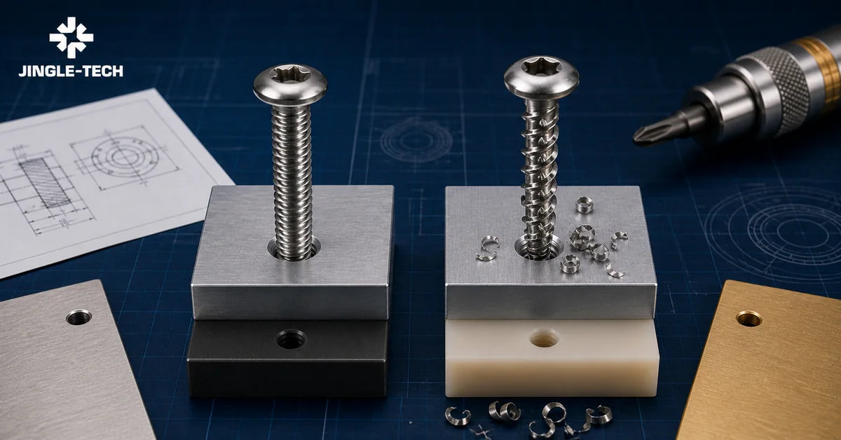
Quick answer: when comparing thread forming vs thread cutting screws, look first at what happens inside the pilot hole. A forming profile pushes the wall material aside and leaves it to flow around the new thread. There is normally no intended cutting chip, but the screw must overcome that material-flow resistance and the hole or boss carries radial load. A cutter does a different job: relieved edges remove material as the screw advances. That can help when the substrate is hard, brittle or heavily filled, although the debris, cutting-edge condition and space at the bottom of a blind hole now need control. Neither mechanism wins in isolation.Try both against production-intent material, hole, finish and tooling, then find the operating space between normal seating and the earliest damaging event. That measured window—not an inherited part name—should drive the choice.
The phrase self-tapping screw creates an early sourcing trap. In one drawing it may mean any screw that makes a mating thread. Elsewhere the same words point to a particular tapping thread, a slotted cutting point, a rolling profile or even a drill point that also creates the starting hole. These are different mechanisms. Do not compare the prices until each bidder writes down what the proposed screw actually does. Otherwise three “compliant” quotations may describe a chipless former, a cutting point and a drill-point product for three different joint stacks.
The correct RFQ therefore begins with mechanism and function.What substrate receives the thread? How is the pilot hole made? Is the hole blind or through? Can the application tolerate chips? How much radial expansion can the boss, casting or sheet feature carry? What clamp load must be retained after polymer relaxation, coating wear or thermal cycling? Will the screw be removed in service? Name the unacceptable outcome before the trial starts. It may be torsional fracture, a stripped thread, a cracked boss, pull-out, head embedment, cross-threading, joint separation or contamination; rank the relevant risks instead of hiding them in one pass/fail line.
This guide turns those questions into a controlled selection process. It separates metal from plastic, describes the variables that change pilot-hole and torque behavior, defines a validation matrix, and gives purchasing teams a quotation return that can compare two proposed screw systems without hiding different assumptions.
Discuss your screw joint and pilot-hole requirements
1. Start with precise terminology
Thread forming means the screw creates the mating thread primarily by displacing substrate material. The local material must flow around the advancing thread profile without unacceptable cracking, tearing, galling or distortion.The operation needs torque to reshape the hole wall, and it creates radial as well as tangential loads. In metal, the process may be described as thread forming, thread rolling or thread tapping depending on the product family and market vocabulary. In plastic, specialized profiles are often designed to reduce radial loading or improve material flow, but a proprietary geometry must be evaluated by its controlled drawing and test evidence rather than by its brand name alone.
Thread cutting means that edges or relief features remove substrate material while the screw moves forward. Less material has to be displaced, but the swarf still needs a destination. A through-hole may let it leave; a blind hole has to provide suitable flute and reservoir space. Ask where every chip could land. Near a seat, insulator, optical surface, seal or bearing, that answer can decide the mechanism. Cutting also should not be treated as shorthand for low torque. A worn edge, hard material, a tight hole, long engagement or a finish change can push the torque trace high—or simply make it erratic.
Self-drilling is a separate function. A drill-point screw creates or enlarges the initial hole before its thread engages. A thread-forming or thread-cutting tapping screw normally starts in a prepared pilot hole. When a project uses the words “self-tapping” and “self-drilling” as synonyms, the RFQ should stop and define the required operations explicitly.
| Term | Primary action | Input that cannot be assumed | Typical sourcing error |
|---|---|---|---|
| Thread-forming screw | Displaces material to create the mating thread. | Substrate ductility, hole and forming torque window. | Assuming chipless installation means low stress. |
| Thread-cutting screw | Removes material through cutting features. | Chip route, cutting geometry and blind-hole space. | Ignoring debris because the screw still reaches depth. |
| Tapping screw | Creates a mating thread in a prepared hole. | Whether it forms, cuts or uses a hybrid lead. | Treating the family name as a complete specification. |
| Self-drilling screw | Produces the starting hole and then engages thread. | Drilling capacity, stack, point clearance and swarf. | Substituting it for a tapping screw without stack review. |
| Machine screw into tapped thread | Engages an existing mating thread. | Thread class, tap process and assembly torque basis. | Using a machine-screw torque rule for a thread-making event. |
The official ASME catalog page lists ASME B18.6.3-2024 for machine screws, tapping screws and metallic drive screws in the inch series. The public listing establishes the current edition, but it does not turn a family name into an application approval. The buyer still has to select the screw type, dimensional designation, substrate and test conditions that belong to the joint.
For ISO tapping-screw threads, the official page for ISO 1478:1999 identifies the second edition as published and confirmed in 2024. That standard is a thread reference. It does not supply a universal pilot hole, boss geometry, cutting strategy or installation torque for every metal and polymer.
2. Use a decision matrix, not a material nickname
“Aluminum,” “steel,” “ABS” and “nylon” are not complete substrate definitions. Metal response changes with alloy, temper, hardness, thickness, casting porosity, hole process and coating. Polymer response changes with exact resin grade, filler type and percentage, moisture, color package, regrind, molding history, weld lines, temperature and aging. The same screw and nominal hole can behave differently when one of those fields changes.
A first-pass decision matrix is useful only if it opens questions rather than closes them.Forming becomes more attractive when the substrate can flow predictably, chip contamination is unacceptable and the boss or hole wall can carry the radial load. Cutting becomes more attractive when displacement would crack or excessively stress the material, when a cutting flute can be cleared, and when chips can be controlled. A hybrid lead may be evaluated when a supplier can explain exactly which part of the geometry cuts, which part forms and how that mechanism is validated.
| Joint condition | Forming question | Cutting question | Evidence before release |
|---|---|---|---|
| Ductile metal with controlled pilot | Can the hole wall flow without galling, bulging or excess torque? | Would cutting add avoidable chips or edge wear? | Torque trace, thread section, strip/pull-out and component distortion. |
| Hard or low-ductility metal | Is forming feasible within screw torsional and surface limits? | Can chips exit and can the cutting feature retain function? | Worst-case hardness trials, chip study and cutting-edge inspection. |
| Ductile thermoplastic | Can polymer flow with an acceptable boss stress and torque margin? | Would cutting reduce stress enough to justify chip control? | Molded-part torque, crack, pull-out and relaxation testing. |
| Brittle thermoset or highly filled polymer | Would radial displacement initiate cracks or split a weld line? | Can chips and notches be contained without degrading the boss? | Microcrack inspection, environmental conditioning and retention tests. |
| Cleanliness-critical assembly | Can forming meet torque and stress limits with no intended chip? | Can every chip be captured, bounded and verified? | Defined contamination limit and representative teardown. |
| Frequent service removal | Will reinsertion follow the formed thread without cross-threading? | Will each cycle recut and weaken the substrate? | Specified removal/reuse sequence or evaluation of a metal insert. |
3. Understand what the substrate experiences
Thread forming is a material-flow process
As a forming lobe or thread crest advances, it compresses and displaces the hole-wall material. The required torque contains more than friction under the head. It includes the work of creating the mating thread, friction on the forming surfaces, friction along already engaged thread, and later the torque associated with seating and clamp load. The local substrate sees circumferential and radial stress. If the hole is too small, material is too hard, engagement is too long, speed creates unfavorable heating, or lubrication changes, torque can rise until the drive recess cams out, the screw twists, the substrate cracks or the hole distorts.
The absence of an intended cutting chip is a process benefit only when material displacement is stable. Formed metal can raise a lip at a hole entrance or exit. A molded plastic boss can whiten, bulge or develop a delayed crack. A cast hole can gall.The drawing should decide whether a countersink, counterbore, entry relief or exit allowance is needed and should define the finished seating surface rather than leaving the supplier to hide displaced material under the head.
Thread cutting is a machining process inside the joint
A cutting screw needs a cutting edge, clearance and somewhere for the chip to move. Cutting torque depends on chip load, edge geometry and condition, substrate, pilot-hole size, engagement and lubrication. If the hole is blind, the unoccupied volume below the screw and the flute volume must accommodate debris without allowing the point or packed chip to bottom out. If the hole is through, exiting chips still need a contamination plan. The screw can appear seated even when debris holds the head away from its intended bearing surface.
Cutting features also change the load-bearing portion of the lead. The buyer should not count every millimeter of nominal screw penetration as full thread engagement. The point, flute and incomplete lead may not carry load in the same way as the full body thread. Screw length, hole depth and effective engagement should be reviewed on a sectioned joint, not inferred from catalog length alone.
4. Selecting a screw for metal
Metal joints require the receiving component to be described at the location of the hole. A nominal alloy designation is not enough if the part is heat treated, case hardened, cold worked, anodized, plated, painted or cast with a hard surface skin.A pierced sheet hole has burr direction and work hardening. A laser-cut hole can have a heat-affected edge. A drilled casting may intersect porosity. An extruded sheet feature changes engagement and radial stiffness. Those conditions can dominate the comparison between forming and cutting.
A forming proposal should state the supported substrate hardness or strength range, hole process, diameter and tolerance, engagement range, entry geometry, required surface condition, screw material/property route, finish/lubrication and installation parameters. A cutting proposal should add cutting-feature geometry, chip path, blind-hole allowance, edge-life or reuse boundary where relevant, and inspection of packed debris or damaged lead threads.
| Metal input | Why forming changes | Why cutting changes | Drawing or test control |
|---|---|---|---|
| Alloy, temper and hardness | Controls material flow and forming torque. | Controls chip formation and cutting-edge load. | Specify range at the hole, not only bulk material name. |
| Section thickness or engagement | Longer engagement increases forming work and torque. | Longer cutting length creates more chip and edge work. | Define minimum and maximum effective engagement. |
| Hole process | Burr, taper and local work hardening affect flow. | Edge condition affects first bite and chip shape. | Name drilled, punched, cast, pierced or machined state. |
| Surface treatment | Can alter friction, hardness and material pickup. | Can load or wear the cutting feature. | Test in final hole condition, including coating. |
| Blind versus through | Needs point and displaced-material clearance. | Needs chip reservoir or controlled exit. | Section the worst-case hole and verify depth stack. |
| Edge distance and local stiffness | Radial expansion can distort a thin wall or split an edge. | A flute can reduce local thread support at the lead. | Validate actual flange, boss, rib and edge geometry. |
The official page for SAE J1237_201709 says that its 2017 revision covers material, dimensional, performance and test requirements for metric thread-rolling screws used in general engineering applications. That scope can support a defined metric rolling-screw purchase, but it does not prove compatibility with an unspecified casting, sheet feature or coated hole. Record the adopted revision and the application-specific validation separately.
Thin sheet needs a thread-engagement decision
In thin sheet, the hole may not provide enough full thread contact to support the required axial load or service cycles. An extrusion, emboss, folded feature, captive nut or insert may be more relevant than changing only the screw. A forming screw can displace material and create a useful thread in a designed feature; a cutter can remove a portion of an already limited wall. Neither statement predicts performance. The joint drawing must show the sheet thickness, feature shape, hole direction, burr/edge condition, mating-part clearance and the full-thread position after seating.
Cast and machined holes need a surface-state decision
In a die casting, draft and as-cast skin may create a tapered, harder or more variable hole. A post-machined hole removes that skin but adds tool-wear variation and burr control.A forming system qualified in a drilled coupon may fail to represent either condition. A cutting system tested in a clean through-hole may behave differently in a blind cast boss. Supplier trials should use production-intent hole creation and the actual minimum/maximum material condition.
5. Selecting a screw for plastic
Plastic selection begins with the exact molded material, not the polymer family. A resin can change from ductile to comparatively brittle with glass or mineral reinforcement, conditioning, temperature, aging or a different color/additive package. Fiber orientation and weld lines around a cored boss may create direction-dependent strength. A pilot hole drilled after molding cuts a different local structure from a molded hole. The product team must decide which of those states represents production.
Thread-forming profiles for plastics often use geometry intended to limit radial stress or improve material flow, but the term “plastic screw” is not a performance specification. The proposal should include the exact thread profile and screw revision, not a generic drawing that hides proprietary lead geometry. Thread cutting may be considered for brittle thermosets or filled grades that do not tolerate displacement, yet the resulting chips and notch effects still require evaluation. For assemblies with repeated service, high retained clamp requirement or weak boss geometry, a threaded insert, captive nut or redesigned joint may be a better baseline.
| Plastic input | Selection effect | Supplier must know | Validation observation |
|---|---|---|---|
| Exact resin and grade | Ductility, creep, friction and strength are grade-specific. | Full commercial designation and approved alternatives. | Torque, cracks, pull-out and retained joint after conditioning. |
| Filler type and percentage | Can reduce allowable local strain and change wear. | Fiber/mineral content and permitted range. | Weld-line and microcrack study at worst orientation. |
| Moisture and temperature | Changes stiffness, friction and relaxation in some polymers. | Condition at assembly and in service. | Dry/conditioned and hot/cold assembly or retention trials. |
| Molded versus drilled hole | Changes skin, draft, fiber path, roundness and size. | Production hole process and inspection method. | Compare production-intent holes, not generic coupons only. |
| Boss and weld-line geometry | Controls hoop-stress capacity and crack path. | Outside diameter, ribs, root radius, edge distance and gate/weld line. | Section, microscopy or another approved crack assessment. |
| Service cycles | Repeated removal can damage the polymer thread. | Authorized reuse count and service method. | Removal/reinsertion torque and final strength by cycle. |
Celanese publishes a grade-specific Celcon POM design guide that discusses both forming and cutting self-tapping designs, pilot-hole control, bottoming prevention and torque-controlled drivers. Importantly, it warns against extrapolating a forming recommendation from an unfilled acetal grade to a named glass-reinforced grade. That is the right sourcing lesson: resin-supplier tables are evidence for the stated grade and geometry, not universal values for all plastics.
6. Pilot-hole design is a controlled product characteristic
The pilot hole is the female-thread blank. Its diameter controls how much material a former must displace and how much material remains for a cutter to engage. Its tolerance defines part of the torque distribution. Its shape controls alignment, thread depth and local stress.A single nominal diameter without process, tolerance, depth and geometry is not enough for a firm screw selection.
For a formed thread, an undersized hole can raise forming torque and radial load; an oversized hole can reduce thread engagement, pull-out and strip margin. For a cut thread, an undersized hole can overload the cutting feature and pack more chip, while an oversized hole can leave insufficient thread height. Those directional statements do not produce a safe percentage engagement rule. Each screw profile, substrate and hole process has a different effective geometry.
| Hole field | Why it matters | Minimum drawing return | Production evidence |
|---|---|---|---|
| Diameter and tolerance | Sets displacement/cutting load and engagement. | Size at specified depth and material condition. | Capability or inspection data using an approved method. |
| Depth and bottom clearance | Prevents point or chip bottoming before seating. | Minimum usable depth and datum. | Sectioned worst-case stack or verified depth measurement. |
| Draft or taper | Changes engagement and torque along the screw path. | Angle, direction and inspection convention. | Top/bottom diameter or profile results. |
| Roundness and position | Controls alignment, local engagement and radial stress. | Datum and geometric requirement where functional. | Representative molded, cast, punched or drilled data. |
| Entry relief | Centers the screw and manages entry bulge or crack initiation. | Chamfer/counterbore dimensions and bearing boundary. | Visual and sectional confirmation after installation. |
| Process and direction | Determines burr, skin, fibers and tool marks. | Molded, drilled, punched, cast or machined state. | Control plan tied to the production process. |
Do not validate only at nominal hole size
A nominal-to-nominal test can hide a joint with no production window. The controlled study should include the smallest and largest permitted hole, minimum and maximum engagement, substrate extremes, screw/finish lots and realistic installation conditions. If a proposed pilot-hole tolerance cannot be held by the chosen molding, casting, punching or drilling process, the correct response is not to approve a narrow theoretical range. The design, process or screw system must change.
Review pilot-hole and installation-window inputs
7. Blind holes make point, depth and debris part of the stack
Blind-hole failures are often misdiagnosed as tightening problems. The screw may reach a torque threshold because the point has bottomed, because cut chips are packed below the lead, because the incomplete thread hits an unplanned taper, or because displaced material has nowhere to move. The controller reports “torque achieved,” yet the head has not created the intended clamp load.
The depth stack should show hole depth from its datum, point length, cutting/forming lead length, chip or displacement allowance, full-thread engagement and the head-seating position. Include tolerance accumulation. For a cutting screw, estimate and verify debris volume through teardown. For a former, inspect entry/exit material and bottom condition. A through-hole removes one bottoming risk but can move chips or displaced metal into a sensitive neighboring zone.
8. Read the torque trace as a process record
A single final torque number cannot tell whether the screw created a sound mating thread.The useful record is torque versus time or angle, synchronized with the process stages. The trace may show initial engagement, thread creation, rundown through the clearance member, head contact and final tightening. A forming or cutting plateau that rises into the seating region can leave too little separation for a stable shutoff. A sudden peak may indicate burr engagement, bottoming, cross-threading or a damaged cutting feature. A low trace can indicate an oversized hole, missing engagement or a stripped boss.
The engineering team should define the accepted waveform or extracted features only after correlating traces with physical outcomes. Useful features may include maximum thread-creation torque, angle or time to head contact, seating slope, final torque, torque at a controlled angle, and alarms for early/late seating. None is meaningful without the tool, speed, bit, downforce, substrate, hole, screw finish and stack used to generate it.
| Trace stage | Expected event | Potential abnormality | Correlated check |
|---|---|---|---|
| Entry | Point aligns and begins thread creation. | Cross-thread, burr strike, misalignment or wrong hole. | Entry geometry, bit alignment and first-thread inspection. |
| Forming/cutting | Mating thread develops along engagement. | Torque escalation, unstable chip, galling or boss stress. | Section, debris, substrate damage and screw lead. |
| Rundown | Screw advances with established thread. | Binding, damaged thread, swarf packing or stack interference. | Free rotation, chip path and effective engagement. |
| Head contact | Bearing surface closes the joint stack. | Early contact, bottoming or debris under head. | Gap, seating surface and depth-stack teardown. |
| Final tightening | Clamp develops within validated limit. | Strip, embedment, torsional fracture or plastic crush. | Clamp proxy, strip/pull-out and bearing-surface inspection. |
ISO 5393:2017 provides a laboratory performance test method for power assembly tools, including measurement of torque repeatability over defined torque rates, settings and cycles. It characterizes the tool under its stated method; it does not establish the safe torque for a particular thread-forming or thread-cutting joint. Tool performance and joint validation are connected records, not substitutes.
NIST's official metrological traceability policy and FAQ makes another important distinction: traceability is a property of a measurement result supported by a documented calibration chain and uncertainty, not a label that belongs to an instrument or organization. When a supplier returns torque data, request the measurement result, method, range, uncertainty where required and chain appropriate to the decision; do not accept “NIST traceable driver” as the entire evidence package.
9. Build an installation window instead of copying a torque value
The lower side of the process window is governed by successful thread creation, full seating and the minimum clamp or functional outcome. The upper side is governed by the earliest unacceptable event: screw torsional damage, substrate stripping, boss cracking, thread pull-out, head embedment, mating-part crush or another product-specific limit. Production variation must fit between those boundaries with a margin established by the responsible engineering and quality teams.
A useful study measures the distributions, not only the averages. Test small and large holes, substrate extremes, screw and coating lots, tool variation, alignment, production speed and environmental states. If maximum drive torque overlaps minimum strip torque, there is no robust setting to select. Raising final torque cannot repair that.The team must change hole, screw, material, engagement, finish, driver strategy or joint architecture.
The official scope of ISO 16047:2005 with Amendment 1:2012 covers torque/clamp-force testing for specified threaded fasteners and explicitly excludes screws that form their own mating thread. It can inform careful thinking about controlled test conditions, but it is not an application test method for the joint discussed here. A buyer should not cite ISO 16047 as though it supplied a tapping-screw installation torque.
10. Design the joint stack, not only the female thread
A sound mating thread can still produce a failed product if the head does not seat correctly. The clearance member must let the screw pass without unintended tapping, the bearing surface must support the head, and the stack must close before the point bottoms. Paint, foam, gasket, soft plastic, ribs and washers can change seating behavior. If the upper member is caught by the screw thread before it contacts the lower member, the joint can “jack” apart and reach torque without clamp.
Specify clearance-hole size, stack thickness, permitted gap, head style, drive, washer or flange, bearing-surface flatness and any countersink. For plastic, evaluate local head embedment and long-term relaxation. For thin metal, check dish or pull-through.If the joint relies on sealing, electrical bonding, positional location or a controlled compression element, define that function separately from the screw's ability to create a thread.
11. Specify screw material, properties, finish and functional tests
A tapping screw must survive thread creation before it can carry service load. The RFQ should define the applicable screw standard and edition, thread designation, head/drive, point and lead, material or grade, mechanical/physical requirements, heat-treatment condition, surface condition, coating, lubricant, corrosion requirement, marking, lot definition and test evidence. Do not mix a thread geometry from one family with a property requirement whose scope does not cover the proposed product.
The official page for ISO 2702:2022 covers mechanical and physical properties and related test methods for heat-treated steel tapping screws with specified ISO 1478 thread sizes under stated ambient test conditions. Its public abstract notes that such screws create mating threads in sheet metals and are not intended to be pretensioned by design. That scope boundary matters: adoption can define a tapping-screw product requirement, but it does not automatically approve a highly pretensioned joint, a plastic boss, or a product outside the stated thread and material range.
For corrosion-resistant stainless tapping screws, ISO 3506-4:2025 specifies defined grades and hardness classes, functional properties and stated temperature boundaries for ISO 1478 tapping screws. The official scope also excludes special properties such as weldability. A stainless material name alone therefore does not establish thread-forming ability in the buyer's substrate, corrosion suitability for the real environment, or compatibility with the selected hole.
12. Treat coating and lubrication as process variables
Finish changes more than color. Coating thickness can alter effective screw geometry, especially at the lead and crest. Conversion layers, sealers, topcoats and lubricants can change friction and therefore drive torque, seating behavior and the apparent margin to strip. A coating lot change can shift a process even when dimensional inspection passes. For cutting screws, deposits or damage at the cutting feature can alter chip formation. For formers, friction and pickup can change the torque needed to displace material.
ISO 4042:2022 covers electroplated coating systems for defined fasteners and includes systems with optional conversion coatings, sealants, topcoats and lubricants. ISO also lists Amendment 1:2026 as published. If that route applies, specify the chosen system and project additions.The standard does not replace joint-specific torque trials, and its hydrogen-embrittlement provisions do not eliminate the need to evaluate screw material, hardness and process risk.
13. Validate the complete tolerance and environment matrix
Validation should reproduce the decisions the production process will make. Begin with screening to compare screw mechanisms and hole concepts. Move to engineering trials on production-intent components. Then establish the installation window and acceptance trace. Finally, verify the process under controlled production variation and service conditions. A coupon can identify a promising geometry, but it cannot approve a molded boss with a weld line, a pierced flange with burr variation, or a coated blind casting.
Do not invent one universal sample size. The number of parts, lots and environmental states must follow product risk, statistical objective, failure consequence and customer requirements. Predefine failure criteria and censored results. If a screw strips before a planned pull-out test, that is a result, not a sample to replace silently. Preserve raw torque/angle traces, part identity, hole measurements, screw lot, tool record and teardown images.
| Factor | Controlled levels | Measurements | Decision supported |
|---|---|---|---|
| Pilot hole | Permitted small, nominal and large conditions; depth/draft extremes. | Actual geometry, thread-creation torque, strip/pull-out and damage. | Whether a manufacturable window exists. |
| Substrate | Material lots, hardness/temper or resin/filler/moisture states. | Torque trace, cracks, thread geometry and strength. | Material range and approved substitutions. |
| Screw and finish | Multiple production-intent screw and coating/lubricant lots. | Dimensions, hardness/properties, drive torque and torsional condition. | Fastener specification and lot controls. |
| Installation | Speed, downforce, alignment, tool/bit and shutoff strategy. | Torque-angle/time features, seating, cam-out and temperature. | Work instruction and monitoring limits. |
| Joint geometry | Engagement, stack, edge distance, boss/rib and bearing extremes. | Gap, clamp proxy, distortion, pull-through and section. | Released drawing limits. |
| Environment/service | Temperature, humidity/conditioning, chemicals, vibration and service cycles as relevant. | Retention, loosening, cracks, corrosion and functional test. | Product-specific approval and maintenance rule. |
14. Diagnose failure modes by evidence
Changing the torque setting without diagnosing the failure often moves the problem. A cracked plastic boss may come from an undersized hole, excessive radial thread geometry, weld-line weakness, cold/dry material, misalignment, a sharp entry or over-tightening. A stripped metal hole may come from an oversized pilot, insufficient engagement, wrong substrate condition or bottoming that was mistaken for seating. A broken screw may point to excessive forming/cutting torque, wrong properties, damaged lead, coating friction or a hard hole.
| Observed failure | Possible mechanism | Evidence to collect | Do not assume |
|---|---|---|---|
| High or erratic drive torque | Small/hard hole, friction shift, dull cutter, galling, misalignment. | Hole, substrate, screw lead/finish, trace and tool alignment. | That a higher-capacity driver fixes the joint. |
| Low drive and low strip torque | Oversized hole, short engagement, weak resin or damaged thread. | Actual hole profile, engagement, material identity and section. | That low installation torque is automatically good. |
| Boss crack or whitening | Excess hoop stress, weld line, sharp entry, environmental stress. | Molding history, crack location, hole, screw profile and conditioning. | That the final torque alone caused it. |
| Head seated with joint gap | Jack-out, point/chip bottoming, trapped debris or upper-member tapping. | Depth stack, clearance hole, underside inspection and trace. | That achieved torque equals clamp load. |
| Loose after aging | Polymer relaxation, embedment, thermal movement or inadequate clamp. | Time/temperature history, retained torque or functional retention. | That initial torque predicts long-term retention. |
| Chips in product | Cutting path, packed blind hole, exit into sensitive zone. | Teardown, particle collection, flute and installation orientation. | That chips remain captured inside the hole. |
15. Convert validation into production controls
A validated screw system can drift if the controlled variables do not reach the shop floor. The product drawing and process documents should identify the screw revision, finish, hole geometry and substrate. The work instruction should define tool, bit, speed, alignment/fixturing, downforce if relevant, sequence, shutoff strategy and trace acceptance. The reaction plan should distinguish a tool alarm from a product nonconformity and should prevent a failed screw from being removed and replaced without a defined repair rule.
Incoming and in-process controls should follow the risk chain. A screw certificate cannot prove the molded hole. A hole gauge cannot prove polymer conditioning. A driver calibration cannot prove that the cutter is sharp or that a forming screw has the correct lubricant. Decide which parameter is checked by drawing inspection, supplier report, process monitoring, destructive audit or functional end-of-line test.
| Control object | Control method | Record | Reaction |
|---|---|---|---|
| Screw identity | Part/revision, lot, dimensions, material/property and finish controls. | Incoming status and applicable test report. | Quarantine mixed or unapproved revision. |
| Substrate | Material/grade/condition and relevant lot trace. | Material and molding/casting/process record. | Hold unauthorized material or condition. |
| Pilot hole | Defined diameter/profile/depth and process checks. | Inspection or capability result by cavity/tool. | Contain affected component lots. |
| Assembly tool | Configuration, verification, bit and maintenance. | Tool status and program revision. | Lock tool and assess product since last valid check. |
| Installation trace | Validated torque-angle/time feature limits. | Result linked to station/product as required. | Follow defined repair/containment; no blind re-drive. |
| Audit joint | Scheduled teardown, strip/pull-out or functional audit by risk. | Lot-linked destructive/functional report. | Escalate trend before process overlap develops. |
16.Ask suppliers for evidence that matches the decision
The supplier return should distinguish product conformity from application suitability. Product conformity answers whether the delivered screw meets the adopted drawing and standard. Application suitability answers whether that screw, hole, substrate and installation process work together in the buyer's joint. A catalog certificate cannot answer the second question. Conversely, a successful application trial does not excuse a screw that fails its specified material, dimensional or functional requirements.
ISO 16228:2017 defines types and content of fastener inspection documents requested at order and states that “test report” is the applicable terminology for its fastener documents. Its official scope excludes specially engineered applications that require other procedures such as initial samples. This is exactly why the RFQ should schedule routine fastener reports separately from a project-specific joint validation package.
ISO 3269:2019 provides a purchaser inspection procedure when no prior agreement exists and a reference process for disputed conformance. The official scope excludes special-purpose and specially engineered applications requiring more advanced control and lot traceability. A custom direct-threaded joint should therefore define acceptance, traceability and application evidence before the order rather than depend on an unstated default.
| Evidence | Quotation stage | Sample/approval stage | Recurring stage |
|---|---|---|---|
| Controlled screw definition | Drawing/standard, revision and proposed deviations. | Approved sample identity and dimensional result. | Revision/lot confirmation as agreed. |
| Material/property | Proposed standard, grade/class and scope statement. | Applicable hardness, torsion or functional results. | Defined test report/declaration frequency. |
| Finish/lubrication | Exact coating system, layers and lubricant status. | Approved lot used in joint trials. | System/lot evidence and change notification. |
| Pilot-hole recommendation | Range tied to exact substrate and screw geometry. | Confirmed window on production-intent parts. | Buyer controls component hole process. |
| Joint trial | Proposed method, equipment, factors and sample plan. | Raw traces, failures, teardown and disposition. | Audit only if defined by control plan/order. |
| Change control | Declared manufacturing, sub-tier and design assumptions. | Approved baseline and open deviations. | Notification/approval triggers in contract. |
17. Build a quote-ready drawing and RFQ package
A buyer does not need to prescribe a proprietary screw manufacturing recipe. The RFQ does need enough information for bidders to quote the same problem. Issue a controlled document index, product drawing or 3D definition, joint section, substrate specification, pilot-hole definition, screw requirement, installation concept, validation/evidence schedule, quantity ladder, packaging/traceability requirement and commercial return template.
Request a compliant base offer and keep alternatives separate. If a supplier recommends a different pilot hole, screw mechanism, finish, head or installation strategy, the alternative should identify the changed drawings, technical rationale, validation work, tooling/process impact, evidence, price and timing. Do not let the attractive alternative silently replace the baseline in the unit-price column.
| RFQ block | Buyer supplies | Supplier returns | Closure before award |
|---|---|---|---|
| Joint function | Loads, clamp/seal/location needs, environment and service cycles. | Mechanism and assumptions affecting proposal. | Authorized engineering acceptance criteria. |
| Substrate | Metal alloy/condition or resin/grade/filler/conditioning. | Supported range and exclusions. | Approved material and substitution rule. |
| Pilot hole | Process, diameter/profile/depth, tolerance, entry and blind/through state. | Recommended range, mechanism and required changes. | Production-capable released geometry. |
| Screw product | Standard/revision or drawing, size, head/drive, length, point and finish. | Exact offered part/revision, manufacturing source and deviations. | One controlled product baseline. |
| Installation | Tool concept, speed, access, alignment, sequence and trace needs. | Proposed settings/window study and equipment limits. | Validated work instruction and reaction plan. |
| Validation/evidence | Factors, stages, acceptance, reports and ownership. | Included/excluded work, method, source, timing and cost. | Approved plan and complete record. |
| Commercial return | Quantity stages, packaging, destination, currency and terms. | Separated screw, tooling, samples/tests and recurring evidence. | Comparable technical and commercial scope. |
Prepare a comparable OEM screw RFQ
18. Normalize quotations before choosing the lower price
Two quotations are not comparable if one forms a thread in the released hole while another assumes a drilled hole change; if one includes production-intent joint trials while another includes only screw certificates; or if one uses a lubricated finish and another an unspecified zinc color. Preserve each supplier's original return, then level the technical baseline before ranking recurring price.
| Gate | Alignment question | Acceptable return | If different |
|---|---|---|---|
| Mechanism | Forming, cutting or hybrid is explicitly defined? | Controlled screw drawing and mechanism description. | Evaluate as separate technical alternatives. |
| Substrate/hole | Same material condition and pilot-hole process/range? | Requirement matrix with declared changes. | Price and validate the component change. |
| Screw scope | Same head/drive, material/property, finish and packaging? | Part/revision and compliance/deviation return. | Requote or normalize documented difference. |
| Validation | Same parts, factors, outputs and approval report? | Stage-gated plan with included cost and source. | Do not compare incomplete evidence as equivalent. |
| Production process | Same tool/trace concept, inspection and change controls? | Implementation scope and recurring requirements. | Separate equipment, fixture or audit cost. |
| Commercial basis | Same quantities, currency, delivery, reports and terms? | Completed common quote-return fields. | Normalize visibly or leave open. |
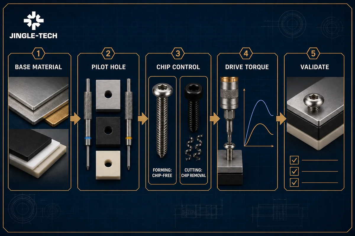
19. Follow a controlled selection workflow
- Define the function and failure boundary. State clamp, retention, sealing, alignment, contamination, service and environment needs.
- Lock substrate and hole states. Identify material extremes, production hole process, geometry and accessible inspection.
- Screen mechanisms. Compare forming, cutting and any justified alternative without mixing their assumptions.
- Select controlled screw candidates. Freeze drawing, material/property, point, finish and lubricant status.
- Measure thread creation and failure. Correlate torque traces with sections, cracks, chips, strip, pull-out and seating.
- Challenge tolerance extremes. Include hole, material, screw, finish, tool and environment variation.
- Approve the full process. Release product drawing, work instruction, trace limits, inspection and reaction plan together.
- Control changes. Define when material, screw, coating, hole process, tool or supplier changes require review or revalidation.
20. Hypothetical metal example: one casting, two different offers
This example is a buyer exercise, not a JINGLE-TECH project or result. An OEM drawing shows a blind pilot hole in a coated aluminum casting but does not state whether the hole is as-cast or machined after coating. Bidder A proposes a forming screw and assumes a machined hole before final surface treatment. Bidder B proposes a cutting screw and assumes a post-coating drilled hole with a chip reservoir. The prices cannot be compared because each supplier has priced a different component process and hole state.
The buyer closes the substrate alloy/condition, hole process, final hole surface, diameter/profile, depth and contamination requirement. Both bidders return their screw drawing, finish, recommended hole window, torque-trace proposal, blind-hole clearance and evidence plan. Engineering tests production-intent casting lots at hole and hardness extremes.Procurement compares only after the technical records show which component changes, tests and process controls belong to each system.
21. Hypothetical plastic example: an unfilled prototype becomes a reinforced production part
This example is also hypothetical. Prototype housings use an unfilled thermoplastic and a thread-forming screw appears stable at nominal hole size. Before launch, the material changes to a reinforced grade and the mold adds a gate that places a weld line across the boss. Reusing the prototype screw and torque would treat the polymer-family name as evidence. It is not.
The buyer reopens the joint decision. The validation matrix includes production-grade material, filler range, molding lots/cavities, weld-line location, moisture/temperature conditioning, pilot-hole extremes, forming and cutting candidates, chip acceptability, boss crack inspection, pull-out/strip and service removal. A metal insert is retained as a third architecture if neither direct screw produces a robust window. The released decision records why one system was selected and which material or mold changes trigger revalidation.
22. Plan for service, repair and reassembly
Removal and reinsertion are separate load cases. A previously formed metal or polymer thread may accept a standard replacement screw only if the thread form, condition and service method are controlled. A cutting screw may recut or damage the path. A technician can cross-thread a former by starting on a new path.Polymer threads can relax or accumulate damage. The service procedure should identify the replacement part, starting method, permitted cycles, inspection, torque strategy and repair disposition.
If repeated service is a real requirement, test the declared number of cycles under aged environmental conditions. Consider a metal insert, captive nut or other replaceable-thread architecture when direct-thread reuse does not maintain the required margin. Do not advertise an unlimited reuse claim from one room-temperature demonstration.
23. Where this joint review connects with other sourcing work
Keep this article as the substrate-and-pilot-hole baseline. When the project moves into a broader made-to-print review, the custom fastener manufacturer and custom screw manufacturer guides cover the adjacent supplier questions without changing the joint assumptions made here.
Other load paths need their own product logic. Use the structural bolt manufacturer page for structural bolting, the concrete anchor manufacturer page for concrete anchorage, and the custom nut manufacturer page when the mating component—not a formed or cut substrate thread—is the purchase focus.
For neighboring product categories, see the hose clamp manufacturer, lifting anchor manufacturer and precast concrete accessories manufacturer resources. Their application risks differ, so use them as separate buying tracks rather than as evidence for this screw joint.
If the assembly also contains turned or milled features, the precision CNC machining parts manufacturer guide addresses that workstream. Buyers combining both categories can use the OEM fastener and machined parts supplier overview to organize the RFQ package.
24. Questions buyers raise during technical review
Does thread forming simply mean self-tapping?
Not quite. Forming is one mechanism for making a mating thread. The broader label “self-tapping” is also used for cutting and other tapping actions, sometimes without saying which one is intended. Put the mechanism, controlled screw drawing and applicable product standard into the RFQ; the family label alone leaves too much room for interpretation.
Do thread-forming screws create chips?
The intended mechanism displaces material rather than cutting it, so it avoids the designed cutting chip. Real components can still shed coating, burr fragments, brittle substrate or debris if the process is unsuitable. Cleanliness-critical applications should verify the installed joint by teardown and a defined contamination assessment.
When should a thread-cutting screw be considered for plastic?
It may be considered when the exact thermoset, highly filled or otherwise low-ductility grade cannot tolerate the displacement stress of a former. That is a screening direction, not a rule. The cutting profile, chips, boss geometry, hole, environmental condition and required strength still need application testing.
Is thread forming always better for thermoplastics?
No. Many ductile thermoplastics can support a suitable forming profile, but grade, filler, moisture, temperature, mold flow, weld lines, boss wall and service requirement can reverse the decision. Validate the production-grade molded part and retain cutting, hybrid or insert alternatives until a robust window is demonstrated.
How do I choose the pilot-hole diameter?
Begin with the controlled recommendation for the exact screw geometry and substrate, then test a manufacturable range that includes tolerance extremes.The drawing must also define hole process, depth, draft/taper, entry, roundness and final surface condition. Do not apply one percentage-engagement rule across different screws, alloys or resins.
Can the same pilot hole be used for forming and cutting screws?
Not without evidence. The two mechanisms use substrate material differently, and their thread profiles and leads may differ. Treat a change of screw mechanism as a joint-design change. Compare each candidate within its proposed hole range and account for any component drawing or process change.
Which option has lower installation torque?
There is no universal answer. Cutting can reduce displacement work, but substrate hardness, chip load and cutting-edge condition can raise torque. Forming torque changes with material flow, hole, friction and engagement. Measure torque distributions on representative joints and compare the margin to strip, fracture, cracking and seating limits.
Why is final torque not enough for process control?
A final value can be reached by correct seating, point bottoming, packed chips, cross-threading or substrate stripping. Torque-angle or torque-time data can separate thread creation, rundown and seating when correlated with physical results. The accepted features must be developed and validated for the specific joint.
Can ISO 16047 set the tightening torque for a tapping screw?
No.The official scope excludes screws that form their own mating thread. It should not be used as a substitute for application-specific thread-creation and seating trials. Define the joint method, tool, substrate, hole, screw and acceptance outcomes directly.
What must be checked in a blind hole?
Check minimum hole depth, point and lead length, full-thread engagement, bottom clearance, tolerance accumulation and the volume needed for chips or displaced material. Confirm that the head seats before the point or debris bottoms and that the process does not force chips into a sensitive area.
How do coatings affect the selection?
Coating thickness and layers can change effective geometry, friction, cutting-edge condition and installation torque. Lubricant may be part of the coating system. Freeze the exact finish used in validation, include production-intent lots, and define change-notification requirements.
Can a thread-forming screw be removed and reinstalled?
Possibly, but reuse is an application claim that must be tested. Reinsertion may follow the existing path or create a new one; plastic threads may relax or accumulate damage. Define the service method, replacement screw, permitted cycles, torque strategy and final acceptance. Use an insert if the required cycles exceed the direct thread's validated capability.
What evidence should a supplier include with the quotation?
Request the controlled screw definition, standard and edition, material/property and finish basis, proposed substrate/hole range, forming or cutting mechanism, installation and validation proposal, deviations, outside processes, sample/test scope, recurring reports and change controls. Keep product-conformity evidence separate from joint-application evidence.
How should two supplier proposals be compared?
First align mechanism, screw revision, substrate, hole, finish, installation, validation and evidence. Then compare recurring and nonrecurring commercial scope on the same quantity, packaging, delivery and currency basis. If one offer changes the component or evidence package, evaluate it as a separate alternative rather than a lower unit price.
When should a metal insert or nut replace a direct screw?
Evaluate another architecture when direct forming or cutting cannot maintain a robust torque/strength margin, when repeated service is required, when boss stress or chips are unacceptable, or when clamp retention exceeds what the substrate can support. The insert or nut then needs its own hole, installation, load and lifecycle validation.
25. Make the selection a controlled engineering record
The practical answer to thread forming vs thread cutting screws is not a one-line preference.It is a chain of evidence: a controlled substrate and pilot hole, a defined screw mechanism and revision, a production-intent installation process, a measured window to every relevant failure, and a supplier return that keeps assumptions and alternatives visible. When that chain is complete, purchasing can compare price without purchasing an unpriced hole change, contamination risk or validation gap.
Before award, walk the joint in both directions. From the product requirement, trace the load, environment, substrate, hole, screw, finish, tool, torque/angle features and evidence. From the quotation, trace every recurring and nonrecurring line back to that same technical baseline. If the two paths do not meet, the bid is not ready for a final ranking.
Request a thread-forming or thread-cutting screw review
Editorial standards check: official ASME, ISO, SAE, NIST and material-supplier technical pages were reviewed on 28 August 2026. Recheck editions, amendments, product scopes and project requirements at the date of RFQ issue.